
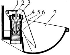
Индивидуальные и групповые автопоилки: для животных. Схемы и конструкции...
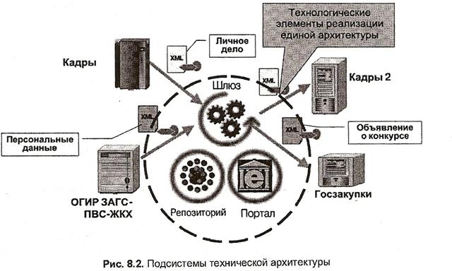
Архитектура электронного правительства: Единая архитектура – это методологический подход при создании системы управления государства, который строится...
Индивидуальные и групповые автопоилки: для животных. Схемы и конструкции...
Архитектура электронного правительства: Единая архитектура – это методологический подход при создании системы управления государства, который строится...
Топ:
Теоретическая значимость работы: Описание теоретической значимости (ценности) результатов исследования должно присутствовать во введении...
Методика измерений сопротивления растеканию тока анодного заземления: Анодный заземлитель (анод) – проводник, погруженный в электролитическую среду (грунт, раствор электролита) и подключенный к положительному...
Интересное:
Что нужно делать при лейкемии: Прежде всего, необходимо выяснить, не страдаете ли вы каким-либо душевным недугом...
Принципы управления денежными потоками: одним из методов контроля за состоянием денежной наличности является...
Искусственное повышение поверхности территории: Варианты искусственного повышения поверхности территории необходимо выбирать на основе анализа следующих характеристик защищаемой территории...
Дисциплины:
|
из
5.00
|
Заказать работу |
Содержание книги
Поиск на нашем сайте
|
|
|
|
One of New York’s most striking new buildings was opened on 17th January by the Governors of the States of New York and New Jersey. This is the bus terminal at George Washington Bridge. On the New York side of the Hudson river. It has been constructed for the Port of New York Authority; its roof was designed by Pier Luigi Nervi.
The new building, which straddles the twelve-lane depressed George Washington Expressway forming the approach to the bridge, is designed to distribute the various bus lines, and some 2,000 busses, which terminate at this point, and to provide a passenger station which will facilitate the daily movement of some 50,000 New Jersey commuters, replacing a number of small terminals scattered over half a mile radius of the bridge head. It will thus bring about two practical improvements: suburban buses to and from New Jersey will be removed from the New York streets, and passengers’ journeys will be shortened by anything from five to twenty minutes.
The three-level bus station, at right angles to the road, is 460 ft. long and 187 ft. wide. The lowest level provides terminal facilities for long-distance buses; the main concourse is at the second level, and the “computer’ bus terminal, with 36 bus-loading island platforms and a continuous unloading platform the full length of the building, is at the top level. The terminal is directly connected by ramps with the upper level of the George Washington Bridge.
The site of the new building is a striking one and the George Washington suspension bridge is itself a striking structure. The terminal had thus to be worthy of its prominent position, and only a designer of the caliber of a Nervi was considered qualified to combine the aesthetic aspect with the solution of the undoubted practical difficulties involved in its construction.
One of the foremost requirements was for constant natural ventilation, which would ensure the removal of bus exhaust fumes even in the lightest breeze. The original scheme was drawn up by the Port of New York Authority to provide for this, with a roof formed of series of units, alternately inclined and horizontal, and with side openings for ventilation. This scheme was, in its broad outlines, retained in the final design.
The lower portion of the structure incorporates structural steel framing to tie in with the suspension bridge approach; from second floor upwards comes Nervi’s striking concrete structure with its wing-like roof. The association of the two materials, however, in itself created an added difficulty in design and construction; special methods of joining the steel and reinforced concrete parts of the structure had to be carefully studied with particular reference to the different elastic characteristics of the two materials.
The final scheme comprises two large reinforced concrete lattice beams along either edge of the building, and a longitudinal spine beam supported on a central row of columns. Spanning diagonally between spine beam and edge beams are lattice trusses, each a right-angle triangle in elevation, so placed that their high points meet on the edge beam. The triangular spaces thus formed between them are in filled by the roof slabs – alternately flat, carried on the lower flange of the trusses, and up tilted, carried on the top flange. Each of these large triangular roof units is made up of a series of smaller triangles, carried on a network of intersecting beams, and topped with a continuous 4 in. concrete slab.
|
|
The whole roof structure is thus a complex of triangles: triangulations in the edge lattice beams; triangles of the diagonal lattice beams; triangles of the wing-like roof sections, triangles making up each of these sections.
The central row of columns carrying the main spine beam is of the subtly twisted section beloved of Nervi, which besides its aesthetic appeal, has the advantage of presenting a minimum obstruction at the base and a maximum supporting surface in the required direction at the top.
The building has an expansion joint midway along its 460 ft., length, and is divided across the width into two 93 ft. 6 in. bays by the central row of columns, which are placed at approximately 65 ft. 6 in. centers.
In construction, the 10 ft. deep spine beam, the bottom flange of the diagonal roof trusses and the horizontal roof sections were cast monolithically, some 550 sq. yds. concrete being placed continuously.
The triangulations of the trusses and their outer end posts were then placed individually on the bottom flanges, and the final stage was to place the concrete of the up tilted roof sections with their network of beams.
The whole structure was cast in situ, and all the concrete is exposed, and left as it came from the forms. Very great care was therefore taken in the choice of mix and the choice of formwork. Experiment and testing of concrete mixes was begun almost two years ago before actual concreting began on site. Altogether 129 different mixes were tested, and nearly 100 test specimens made up with variations of mix, type of formwork, form liners and coatings, and methods of compaction. Finally a specimen roof panel was made up and tested, using plastic-lined forms; these tests showed some instability in the plastic linings under temperature changes, and eventually plastic-coated plywood was used. A test section of the lattice edge beam was also made up for approval of the finished surface.
Formwork for the columns and trusses was designed to give the concrete a definite board-marked pattern, using butt-jointed pine boards. The roof covering units, on the other hand, were given an extremely smooth surface by casting them against the plastic coated plywood.
Constructing a skyscraper
New methods in the design and construction of skyscrapers have been closely related to the development of computers. Engineers use computers to solve the complex mathematical problems involved in such construction projects. Computers do this work quickly by breaking the design down into a limited number of recalculated elements.
When an organization decides to erect a skyscraper it usually signs a contract with building firm. The company awards the contract after many firms have submitted bids showing the price they will charge and the time they will need to erect the building. The company that receives the contract must make detailed building plans that construction can be done as quickly and as cheaply as possible. The construction firm often subcontracts to other companies such work as electrical wiring, plumbing, and bricklaying. Such subcontracting saves money because it means using a worker only when the production schedule requires the individual’s services.
|
|
Before construction begins, engineers determine the strength of the soils that will lie underneath the new building. With this information, they can design the proper foundation. After the building site is cleared, leveled, and drained of water, excavation (digging) begins. Mobile diggers usually excavate the foundation. Ground made of rock may be excavated by blasting.
Sometimes workers dig a trench on all sides of the foundation and fill it with concrete before excavation begins. Any excavation that may cave in is braced and shored with wood or steel. Pumps can be used to keep water from the excavation area at all times. But if the soil becomes too watery, caissons (protective walls) may be built so the work can continue.
After the excavation is finished, the footings (base) and the superstructure are built. Most steel used in the superstructure, such as beams, girders, and columns comes prefabricated. Each piece of steel should have a number indicating the exact place where it should be used. When the steel is raised into place, workers fasten the pieces together temporarily with bolts. Later, welders and riveters join these pieces together permanently.
Most kinds of derricks and cranes are used in the construction of skyscrapers. The two main kinds are mobile cranes and tower cranes. Mobile cranes are mounted on trucks or special vehicles and can maneuver around the outside of the building to hoist materials and equipment from various locations. Tower cranes are supported on a steel tower erected next to or inside a building’s framework. They can only hoist materials positioned within the maximum radius of their lifting mechanisms. Some tower cranes can add sections to increase the height of their support tower as the building goes up. Others are mounted directly on the recently constructed upper storey of the building’s framework. A derrick, mobile crane, or even a helicopter can help in removing sections of a tower crane once the building is nearly complete.
After workers complete the superstructure and outside walls, the building is ready to be finished, decorated, and furnished.
Often used in high class work as a finishing to a reinforced concrete roof slab, but very seldom to timber flat roof construction.
The old method of soldering metal sheets together has now been largely replaced by welted joints, which are made by a special efficient mechanical device. The welted joint, executed in this way, is a rather rapid means of jointing and effectively allows for expansion and contraction of the metal covering.
|
|
|
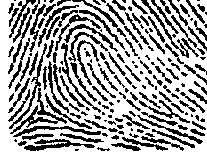
Папиллярные узоры пальцев рук - маркер спортивных способностей: дерматоглифические признаки формируются на 3-5 месяце беременности, не изменяются в течение жизни...
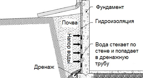
Общие условия выбора системы дренажа: Система дренажа выбирается в зависимости от характера защищаемого...

Историки об Елизавете Петровне: Елизавета попала между двумя встречными культурными течениями, воспитывалась среди новых европейских веяний и преданий...
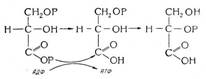
Биохимия спиртового брожения: Основу технологии получения пива составляет спиртовое брожение, - при котором сахар превращается...
© cyberpedia.su 2017-2024 - Не является автором материалов. Исключительное право сохранено за автором текста.
Если вы не хотите, чтобы данный материал был у нас на сайте, перейдите по ссылке: Нарушение авторских прав. Мы поможем в написании вашей работы!

