
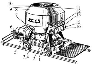
Кормораздатчик мобильный электрифицированный: схема и процесс работы устройства...
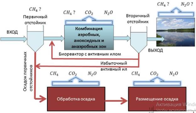
Эмиссия газов от очистных сооружений канализации: В последние годы внимание мирового сообщества сосредоточено на экологических проблемах...
Кормораздатчик мобильный электрифицированный: схема и процесс работы устройства...
Эмиссия газов от очистных сооружений канализации: В последние годы внимание мирового сообщества сосредоточено на экологических проблемах...
Топ:
Процедура выполнения команд. Рабочий цикл процессора: Функционирование процессора в основном состоит из повторяющихся рабочих циклов, каждый из которых соответствует...
Отражение на счетах бухгалтерского учета процесса приобретения: Процесс заготовления представляет систему экономических событий, включающих приобретение организацией у поставщиков сырья...
Методика измерений сопротивления растеканию тока анодного заземления: Анодный заземлитель (анод) – проводник, погруженный в электролитическую среду (грунт, раствор электролита) и подключенный к положительному...
Интересное:
Лечение прогрессирующих форм рака: Одним из наиболее важных достижений экспериментальной химиотерапии опухолей, начатой в 60-х и реализованной в 70-х годах, является...
Аура как энергетическое поле: многослойную ауру человека можно представить себе подобным...
Берегоукрепление оползневых склонов: На прибрежных склонах основной причиной развития оползневых процессов является подмыв водами рек естественных склонов...
Дисциплины:
|
из
5.00
|
Заказать работу |
Содержание книги
Поиск на нашем сайте
|
|
|
|
New research by the Transport Research Laboratory has identified the loading requirements and investigated various compressible materials which may be suitable for use as innovative structural backfill behind integral bridge abutments.
Investigations have confirmed, that most bridge deck expansion joints leak and contribute more than any other factor to corrosion of the deck by de-icing salts. For this reason joint-free integral bridges are more durable and cheaper to maintain.
However, thermal expansion and contraction of an integral deck may lead to the development of very high soil pressures behind the abutments. Traditionally thorough compaction of high quality granular backfill has been used behind bridge abutments to avoid settlement of the carriageway. In an integral bridge, however, better quality backfill accentuates the risk of high soil pressures developing.
Integral bridge design has therefore to accommodate or avoid the high forces and bending moments that may develop in the structure. One method of avoiding high soil pressures on the abutments is to use an elastic cushioning layer, thus allowing more economical design of new integral bridges. In addition, the method may also provide an economical conversion of existing conventional bridges into integral structures as part of the need to reduce long term maintenance costs. The TRL has also developed a laboratory test to quantify the capillary suction properties of concrete.
Corrosion of reinforcement caused by chloride penetration of concrete cover is a problem which affects many bridges worldwide. In many cases the corrosion starts much earlier in the life of a bridge than expected. This suggests that factors other than the historically accepted properties of concrete strength and permeability need to be taken into account.
Research on chloride ingress into structural concrete, carried out for a number of years at TRL, has shown that capillary suction is an important mechanism by which chloride is absorbed. The absorption is fast-approximately one million times faster than the movement of chloride through concrete by permeability processes. TRL say current guidance on the design of concrete mixes for durability does not take capillary suction into account. The test procedure uses cubes of concrete placed on foam, saturated with either water or salt solution, and the quantity of liquid absorbed is determined by measuring the weight change of the cubes. In order to reproduce, to some extent, the conditions experienced on site, the cubes are subjected to a cyclic wetting and drying regime, rather than to a continuous period of wetting.
Distances of penetration of the liquid can be calculated if the porosity of the concrete is known, and chloride concentrations are determined by drilling the cubes to different depths and analyzing the drilling dust for chloride content. Research aimed at reducing the time taken to carry out a test is currently in progress.
Germany ’s highway vision
|
|
The Verkehrsprojekt Deutsche Einheit (VDE) is a building program that aims to bring East German roads up to the standards of the west. So far 11 000 km of roads have been built or rebuilt. Next year, $1,6 billion is allocated to road construction in the east. The government’s goal is to make the seven large motorway projects operational in significant parts by the turn of the century. These roads total 2000 km, of which 150 km is now usable and a further 440 km is already under construction.
The three road widening projects, from four to six lanes, are showing the most progress. Many sections are complete, and about 310 km is under construction including the A2/A10 Hannover-Berlin Ring, The A9 Berlin-Nuremberg and the A4 Eisenach-Dresden.
Marrying a sustainable environmental policy with widespread construction is another challenge the country faces. In western Germany, 440 km of new motorway was built, and 163 km was widened from four to six lanes. An additional 650 km of roads were also built, most of these being bypasses. These bypasses play a central role in the government’s environmental policy and a further 52000 km is planned. Just in the last year, 37 bypasses with a length of around 200 km have been built at a cost of $600 million. The government has also invested $3 billion to date in noise protection and has 2 000 km of noise barriers installed along roadsides.
Transport minister Matthias Wissmann says: “We can say this with pride: No country spends as much as we do on the environment and noise protection. That should stay that way!”
Reduced pollution is one of the benefits of intelligent transport systems (ITS), which the government is supporting, through its own economic forum. Wissmann sees the other opportunities that modern communication and information technology offers as being:
- better use of the available infrastructure, especially by increasing capacity at bottlenecks and smoothing the traffic flow;
- better coordination between the different modes of transport, spreading the burden equally;
- avoidance of unnecessary jams and unladed journeys, including motorists seeking parking spaces;
- improvement in safety.
The transport minister says that the intelligent transport industry has reached the stage now where close cooperation between transport policy makers and industry can significantly accelerate a widespread introduction of the technology.
Forming a tunnel
Europe’s most current important infrastructure project, a key element of the Oresund 16 km long bridge/tunnel link between Denmark and Sweden is the 3,7 km Drogden road tunnel.
This immersed tube structure will be the largest in the world, with the 42 m wide and 8,5 m high tunnel segments produced on land using the incremental launching methods, in use for the first time for a tunnel.
Production of the 20, 178 m-long elements making up the tunnel requires massive concrete placement and the use of formwork. Each of the tunnel elements is composed of eight 22,5 m-long segments, making a total of 160 tunnel segments, calling for 80 reuses per formwork assembly. The segments do not have any horizontal joints, and in view of the large number of segments and the need for top quality concrete, a method was needed that was based on factory prefabrication methods.
The segments were cast in a weekly cycle in a special plant in North Harbor, on the outskirts of Copenhagen. The requirements were stringent. Since the final position of the tunnel will be under the sea, the outer walls must be watertight.
|
|
The formwork must have only two levels of formwork ties in the wall height of 8,5 m and the holes must be watertight sealed. To achieve this the company is using the concrete cones bonding technique whereby the cones are bonded to the tie holes using a two component adhesive with granulate, which prevents the cones from setting during bond hardening.
A further challenge was the adaptability of the formwork to the changes in the cross-section of the tunnel geometry. The thickness of the tunnel bottom slab varies, as does the roof slab strength. However, the greatest difficulty is the alignment of the longitudinal incline of the tunnel segments. Some 50 different adjustments are required to the formwork in order that the entire tunnel profile is guaranteed.
Like the formwork of an incremental launching bridge, the base and external formwork is fixed. The inside formwork forms two motorway and two railway bores and one service gallery. Due to the monolithic construction, the inside formwork units must not be supported within the 22,5 m long segments, but suspended on giant lattice girders. These are supported outside the casting section. One lattice girder is 50 m long, 4m high and weighs 53 t. The total weight of the formwork assemblies is 2 300 t.
During the casting procedure, the entire dead weight of the segment and the dead weight of the inside formwork transfer to the bottom formwork. The load of about 7 500 t is distributed over 250 compression braces and conducted into the casting yard.
A casting procedure takes between 32 and 40 hours without interruption. After a segment has been cast and cured, bottom and outside forms are struck as in a bridge incremental launching plant, and the segment, together with the inside form, is then pushed forward one step on skidding beams.
Once the reinforcement — in this case a complete prefabricated reinforcement cage of 380 t dead weight — has been positioned for the next casting section, the inside formwork is retracted from the moved completed tunnel segment into the reinforcement and into the starting position for the next casting section.
The 50 m-long lattice girders serve as a “track” on which the inside formwork is hydraulically transported 22,5 m each time. This formwork procedure is repeated eight times, until a tunnel element of 178 m length is completed.
Bridge or Tunnel?
Should a motorway pass under or over a large waterway? For a narrow waterway there is no problem, the water is always bridged. Until 1960 only two alternatives existed, bridging over or tunneling under the waterway, but now a third choice is available, the immersed tube is made by lowering pipes of great length into a trench in the bed of the sea or river, and joining them under water.
The main considerations in the decision are now generally traffic capacity, gradient, obstruction of shipping, costs of construction and maintenance, speed of completion, possible later widening and so on.
The choice often falls on a bridge because it can carry more vehicles per hour and its capacity is more easily extended by widening or by adding a deck.
One of the largest bridges in the world, with twelve traffic lanes, six on each of its two decks, is the Verrazano-Narrows Bridge in the New York. For many years the United States Army engineers would not allow a bridge to be constructed at this site because its destruction in war time could block the harbor, and they insisted on building a tunnel. But after the first atomic bombs had been exploded, the U.S. Army saw that it was purposeless to continue to insist on a tunnel.
In the eightieth of the last century, also for military reasons, the British government would not allow further work on the tunnel under the English Channel to France although the preliminary work was by then so advanced that lengths of 1 km of pilot tunnel of some 2 m diameter had already been driven from each shore. These lengths were still in perfect condition when inspected eighty years later, because they had been driven through a chalk rock which is ideal for tunneling, being fairly watertight and just strong enough.
The ever increasing motor traffic needs an ever growing number of highways, which will have to cross important waterways, with also increasing shipping. In several cases tunnels will not only be the cheapest solution, but also the best with regard to weather conditions (no ice or snow, no wind or rain), maintenance, danger of collision with a ship, aesthetic reasons, etc.
Bridge/tunnel combinations form attractive and often obvious solution for crossings of great length.
It is easy to predict that in the next decades an ever increasing number of important and interesting tunnels — submerged or bored — will be built, and that the existing methods of building, sinking, etc. will be improved and perfected and new and astonishing techniques will be developed.
|
|
|
Организация стока поверхностных вод: Наибольшее количество влаги на земном шаре испаряется с поверхности морей и океанов (88‰)...
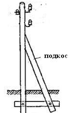
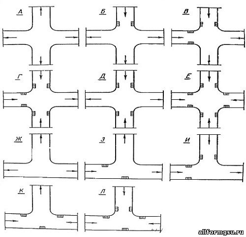
Опора деревянной одностоечной и способы укрепление угловых опор: Опоры ВЛ - конструкции, предназначенные для поддерживания проводов на необходимой высоте над землей, водой...

Историки об Елизавете Петровне: Елизавета попала между двумя встречными культурными течениями, воспитывалась среди новых европейских веяний и преданий...
Эмиссия газов от очистных сооружений канализации: В последние годы внимание мирового сообщества сосредоточено на экологических проблемах...
© cyberpedia.su 2017-2024 - Не является автором материалов. Исключительное право сохранено за автором текста.
Если вы не хотите, чтобы данный материал был у нас на сайте, перейдите по ссылке: Нарушение авторских прав. Мы поможем в написании вашей работы!

