Abstract – To pursue intelligence is our research purpose. By considering knowledge from related research fields such as psychology, biology, cognitive science, physiology, etc., we have managed to take into account three factors, i.e. to have a physical body to be able to interact with the environment, to implement a hierarchical structure for intelligence and not to prepare modules expressing functional similarities a priori. By applying harmony theory – a mathematical model produced in the field of cognitive science – we succeeded in implementing these three factors and creating a hierarchical structure for robot intelligence. The greates asset of this research is that we do not have to prepare functionally isolated modules a priori. The Harmony Theory Network (HTN) automatically organizes the robot behavior in a hierarchical manner as robot intelligence in relation to the environment. That is to say, we find that differences in the environment influence the structure of the HTN, the structure of the HTN acknowledges differences in sensor tasks automatically, the HTN organizes the connections for sensory and motor processing in its lower layer, and coordinates the well-organized robot behavior in its higher layer by combining the sensory-motor relation obtained by the lower layer, and it is possible to interpret the meaning of the HTN structure afterwards in relation to the robot behavior.
Keywords: embodiment; learning; development; cognition; adaptation; neural networks; artificial intelligence.
INTRODUCTION
Numerous studies have been carried out in an effort to determine how a human being functions. There have been many attempts to evaluate the mechanism of our cognitive and brain functions, particularly intelligence, since the end of the last century. Nevertheless, we are still far from having a clear picture of how the human brain works in relation to intelligence. The purpose of this study is to establish a methodology in order to pursue the essence of intelligence using robots. We have especially taken into account the hierarchical structure of the brain and attempted to implement this to produce robot intelligence. By investigating the development of robot intelligence, we have explored the nature of intelligence in this study. Firstly, let us discuss research which has already been performed in related fields.
As W. James said:
“... the study of the distribution of consciousness shows it to be exactly such as we might expect in an organ added for the sake of steering a nervous system grown too complex to regulate itself... an Ego must be added to the bundle to give it unity, and bring the variety of consciousness into relation with each other”.
We can imagine the consciousness and ego being produced only when the system (the mechanism for generating intelligence in this case) is complex and diverse enough. It is not clear how complex and diverse the system should be though, but it is clear that we cannot create a robot with a consciousness or ego resulting from a complex system using the technology we have at present. However, it would seem reasonable to pursue and analyze the functions of human intelligence, and attempt to create Artificial Intelligence (AI) similar to the intelligence of human beings.
In the field of biological research, the knowledge we have of the brain is that it basically consists of neurons. These work in varying ways depending on their location within the brain. The route and structure necessary to produce intelligence is produced by the sensory-cognitive-motor system. This corresponds to the lower sensory area-higher sensory area-highest sensory area-highest motor area-higher motor area-lower motor area in the cerebral cortex. Information flows from a lower to higher module of the sensory system and a higher to lower module of the motor system. Thus, we know the mechanism for information flow in the brain, although we do not clearly know what kind of process is taking place there, especially with regard to the process of connection between modules. Therefore studies in this field have provided insufficient information to create a computational model of the brain.
The target of classical AI research was to produce a decision mechanism for the process by which the sensory and the motor systems are connected. However, since the decision mechanism was produced only for connecting the two systems, its construction by rules or maps could not handle novel information from the sensory system. Nowadays, the community of adaptive behavior researchers insists that AI cannot be separated from the subjective experience of the body, and the essence of intelligence is the interaction between this body and the environment. This concept has become the main stream of AI study in relation to robotics as new AI.
In summary, the essence of the new AI is:
1) to have a physical body;
2) to interact with the environment; and through the interaction between the physical body and the environment;
3) we can expect the emergence of intelligence.
OPERATIONAL AMPLIFIERS
The operational amplifier (op amp) has a short but eventful history. The concept of the op amp dates back to the late 1940s, when they were used in analog computers. They performed the mathematical operations of addition, subtraction, integration, and differentiation; hence, the name operational amplifier. The original op amp was constructed mainly of vacuum tubes. Those early op amps consumed a lot of power and were costly and bulky.
The integrated circuit op amp as we know it today was developed in 1965 by Robert Widlar. Widlar was then working for Fairchild Semiconductor, which marketed the first integrated circuit op amp, the μA709. The 709 was so well designed that it is still in use today. In the intervening years, that one design has been further developed and expanded. Today, it is estimated that there are several thousand types of op amps. Furthermore, over one-third of all linear integrated circuits (ICs) are op amps. In fact, the op amp is one of the most popular active linear devices on the market today. The reason for its popularity is threefold. First, many different kinds of op amps are commercially available, and they are low in cost. Second, as we will see later, the op amp displays enormous versatility in application. Third, op amps are easy to use in designing and developing prototypes.
Just what is an op amp? We can describe an op amp very simply as a high-gain, direct-coupled amplifier. Characteristics such as circuit gain and frequency response are established by external components.
In this chapter, we will look at several important features of the op amp, such as their symbols, parameters, and configurations. We will discuss the ideal op amp, with a brief look at how the internal structure affects the performance of the device. After considering the ideal op amp, we will spend the remainder of the chapter dealing with practical op amp circuits and configurations. We will also introduce the two major classifications of op amp circuits: the inverting and noninverting op amp.
Ideal Op Amp
If asked to describe the perfect or ideal amplifier, what characteristics would we choose? For instance, what should the gain, frequency response, and input and output impedances be? If small signals are to be amplified, certainly we would want the voltage gain to be high, ideally infinite (Av = ∞). (Note that we use A to symbolize gain, although G is sometimes used in other textbooks.) Again, if the input signal is very small, we do not want the amplifier to load down (reduce) the signal. So, ideally, the input impedance should be infinite (Zj = ∞). What about frequency response? If an amplifier is to be versatile, it should amplify (ideally) any signal from 0 Hz (DC) to infinity (bandwidth BW = ∞). Finally, what is the ideal output impedance? There are basically two conditions we need to think about in choosing an output impedance: maximum transfer of power and maximum transfer of voltage. Since the op amp is not a power device, we do not need to worry about matching impedances for maximum power transfer. If the output impedance of the op amp is zero, we have maximum transfer of voltage, which is what we want. Also, if the output impedance is high, the gain of the amplifier is reduced. The output impedance forms a voltage divider with the load and feedback resistors. Ideally, then, the amplifier's output impedance should be zero (Z0 = 0Ω).
We do not normally need to be concerned with the internal workings of the op amp. However, a brief consideration of the op amp's internal circuitry is helpful in understanding how the ideal op amp parameters are so nearly achieved. It also gives some insight into the limitations in testing and measuring op amp performance.
output impedance is high, the gain of the amplifier is reduced. The output impedance forms a voltage divider with the load and feedback resistors. Ideally, then, the amplifier's output impedance should be zero (Z0 = 0 Q).
We do not normally need to be concerned with the internal workings of the op amp. However, a brief consideration of the op amp's internal circuitry is helpful in understanding how the ideal op amp parameters are so nearly achieved. It also gives some insight into the limitations in testing and measuring op amp performance.
SURVEY OF ELECTRONICS
Electronics and radio communications are practical applications of the general principles of electricity. The same electricity produced by a battery for a flashlight can be modified to do any number of jobs, from running a motor or producing heat and light to more advanced uses such as working a computer or providing wireless broadcasting for radio and television.
The word radio is an abbreviated form of radiotelegraph or radiotelephone. In its first form, wireless communication was by radiotelegraph, using short dots and longer dashes as symbols for letters in the Morse code. Now radiotelephone is used more, providing wireless voice communications or broadcasting voice and music programs for entertainment. In general, then, radio is the art of wireless communications.
The word electronics derives from the electron, which is a tiny, invisible quantity of electricity present in all materials. In terms of its many uses, electronics can be defined to include all applications of electricity flowing in a vacuum, as in vacuum tubes, in gas or vapor, and certain solid materials such as transistors. More generally, electronics includes all effects of electricity where the action of individual electrons determines the application. The main electronic devices are transistors and vacuum tubes.
Radio and electronics are closely related. Sometimes they are even joined in their use. For example, an electronic heating unit generates radio waves that go through the work to produce heat. The heat bonds the solid materials together. Even if the applications are not so close, the principles of radio and electronics are essentially the same. Both are based on the fundamental laws of electricity.
DEVELOPMENT OF ELECTRONICS
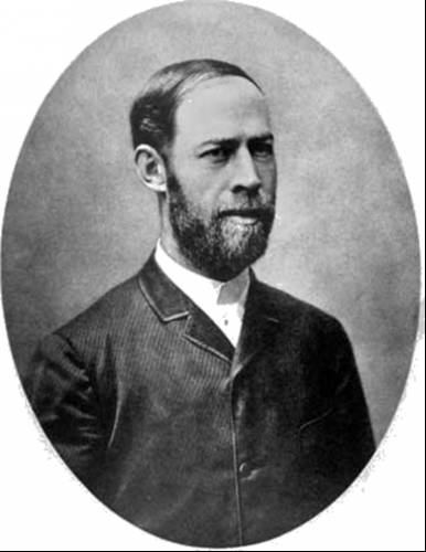
Wireless transmission can be taken as starting with the work of Heinrich Hertz, a German physicist. In 1887 he was the first to demonstrate by experiment the process of electromagnetic radiation through space. The distance of transmission was only a few feet. However, it demonstrated radio waves traveling from one place to another without the need for any connecting wires between the transmitting and receiving equipment.
Hertz proved that radio waves, although invisible, travel with the same velocity as light waves. In fact, radio waves and light waves are just two examples of electromagnetic waves, a form of energy that combines the effects of electricity and magnetism. Additional examples of electromagnetic waves include heat radiation, x-rays, among others, all of which can transmit energy through space without the need for any connecting wires.
The work of Hertz followed earlier experiments on electricity and magnetism. In 1820, a Danish physicist, H.C. Oersted, snowed that an electrical current produces magnetic effects. Then, in 1831, a British physicist, Michael Faraday, discovered that a magnet in motion can produce electricity. In 1864, the British physicist James Clerk Maxwell, on the basis of work in electricity and magnetism, predicted the electromagnetic waves demonstrated later by Hertz.
In 1895, Guglielmo Marconi used a long wire antenna and developed a practical radio system for long-distance communication. He succeeded in producing wireless communication across the Atlantic Ocean in 1901.
The rapid advances after that are due largely to the introduction and progress of the vacuum tube. In 1906 Dr. Lee Forest, with his audion tube that could amplify electric signals, was leader in this field.
As the design of vacuum tubes advanced, radio broadcasting progressed rapidly. Regularly scheduled programs were broadcast in 1920 by station KDKA in the AM (amplitude modulation) radio band. The commercial FM (frequency modulation) broadcast service for sound programs was started in 1939. Stereo broadcasting in the FM radio band began in 1961.
With regard to television, after discarding previous mechanical systems that used rotating drums or disks, commercial television broadcasting was adopted officially in July 1941, although its popular use did not begin until 1945. Our present color-television system was adopted in 1953.
Now, with the invention of transistors in 1948 at Bell Telephone Laboratories, there are new applications in electronics and radio. The transistor is an application of controlled electron flow in solids such as germanium and silicon. Tubes and transistors both have similar applications for amplification or control purposes. The transistor is smaller, however, and more efficient because there is no heater. Solid-state electronics using semiconductors includes not only transistors and diodes but also the integrated circuit (1C). It combines semiconductor components in one solid chip with the required resistors and capacitors.
Radio Broadcast Services. Broadcasting means sending out in all directions. The transmitter radiates electromagnetic radio waves in all directions by means of its antenna. Receivers can pick up the transmitted radio waves by means of a receiving antenna of aerial. Practically all radio receivers now use transistors instead of vacuum tubes.
The carrier is an electromagnetic radio wave that includes the variations of the desired voice or music information, inserted by modulation. This technique of modulating a carrier wave is necessary because the desired information itself is not suitable for wireless transmission. The carrier is chosen for the best radio transmission; the modulation provides the information. For the amplitude modulation (AM), the amplitude of the carrier wave varies with the modulation. In frequency modulation (FM), the modulating voltage varies the frequency of the carrier wave.
Frequency is an important characteristic of an alternating voltage or current. How many times per second the carrier wave varies through a complete cycle of reversals in polarity is the frequency in cycles per second (cps). The unit is the hertz (Hz), where 1 Hz = 1 cps.
The transmission distance may be 10 or 5000 miles, depending on the type of radio service. There are many services for different uses, including broadcast radio and television for home entertainment, radio navigation, maritime radio, police radio, amateur radio broadcasting, government radio services, and many others. These are all regulated by the Federal Communications Commission (FCC) in the United States. The FCC assigns the carrier wave to be used by the broadcast station.
Standard Broadcast Band. This band is the original system of broadcasting for what we generally call radio, using amplitude modulation in the transmission of the station's assigned carrier wave. The AM radio band is 535 to 1605 kHz. The last digit is not on the dial.
FM Radio Band. This band is 88 to 108 MHz. The FM system reduces static and interference. Also, the FM band is used for broadcasting high-fidelity audio signals. For stereo broadcasting, the left and right audio signals are multiplexed, or combined, on one carrier wave.
Television Broadcasting. Television is just another application of radio broadcasting. Two separate carrier signals are transmitted by the station in its assigned channel. One is the AM picture signal; the other is the FM sound signal. A TV channel is 6 MHz wide to include the picture and sound signals. As an example, channel 4 is 66 to 72 MHz. For color broadcasting, the color signal is multiplexed with the black-and-white signal on the one carrier wave for a picture signal.
Marine Radio. This use is important for ship navigation and safety. In addition to ship-to-ship and ship-to-shore communications, radio is the basis of radar navigation systems.
Aeronautical Radio. In addition to communications, radio is an important part of air navigation. It includes radar, radio compass, radio range, and automatic landing equipment.
Government Radio. There are many radio stations operated by the federal government for civilian and military requirements.
Industrial Radio. Radio waves are used for industrial, medical, and scientific equipment. Examples are the diathermy machines used by doctors and industrial heating equipment.
Amateur Radio. This is perhaps the largest noncommercial radio broadcast service. These self-styled "hams" usually build and operate their own transmitters and receivers to call each other in one of the assigned amateur radio bands. The largest organization in this field is the American Radio Relay League (ARRL), Newington, Connecticut.
Industrial Electronics. These applications include welding, dielectric heating, induction heating, metal detector, smoke detector, moisture control, and computer-controlled machinery. In addition, there are many types of remote-control units, including automatic garage door openers and burglar alarms. Closed-circuit television is often used for surveillance.
Supersonics or Ultrasonics. Electronic equipment also uses sound waves with frequencies above the range of human hearing. Examples are sonar equipment for marine depth equipment, ultrasonic cleaning machines, and remote control units for tuning television receivers to different channels.
Classifications. There are so many applications that they are generally considered in these broad categories:
1. Radio communications. This includes AM radio, EM radio, including stereo, and
television broadcasting, including color. Radio can further be subdivided between
receivers and broadcast equipment, either at the transmitter or at the studio. High-
fidelity audio equipment can be considered a specialized branch of receivers.
2. Electronics. Some of the main subdivisions are computers, industrial control,
servomechanisms, testing and recording instruments, and medical electronics. The
applications of computers, including EDP, probably form the largest branch of electronics.
3. Electrical power. Generation, distribution, and uses, including dc and ac
machinery.
Branches. Specific divisions in radio and electronics are indicated by the following specialized titles for engineers: aeronautical, audio, antennas, communications, computer, engineering management and etc.
AUTOMATIC MIXER
The tank in the diagram is filled with a fluid, agitated for a length of time, and then emptied. A state description is similar to a flowchart in computer programming. This sequential process is the kind of process that can easily be handled by a programmable controller.
A ladder diagram is a diagram with a vertical line (the power line) on each side. All the components are placed between these two lines, connecting the two power lines with what look like rungs of a ladder - thus the name, ladder diagram. The letter symbols in the diagram are defined in succeeding paragraphs.
Relay ladder diagrams are universally understood in industry, whether in the process industry, in manufacturing, on the assembly line, or inside electric appliances and products. Any new product increases its chances of success if it capitalizes on widely held concepts. Thus, the PC's ladder diagram language was a logical choice.
Some mention should be made at this point about electrical and electronics symbol designations, hi general, there is a difference between electrical and electronics symbols and symbol designations. These two industries grew up somewhat independent of each other, and therefore differences exist. For example, the electronics symbol for a resistor is a zigzag line with a symbol designation of ri. The same symbol in the electrical or industrial world is a rectangle with lines out the ends and with a symbol designation of 1R. These differences can sometimes be confusing. In this chapter, we will use the industrial symbols and symbol designations because the programmable controller developed as an industrial machine.
Now, let us follow the series of events for the full control cycle the automatic mixer process. At the start of the process, the start push button (1PB) is pressed. The start button energizes a control relay (1CR) located in the start/stop switch box.
It is located in the first line, or rung, of the ladder diagram. They are shown in the normally open position (abbreviated NO). The same symbol with a slash drawn through it represents the normally closed (NC) relay contact.
When the relay (1CR) is energized (or pulled in or picked up), these relay contacts change state; in this case, they close. When the 1CR contact under the 1PB switch closes, it allows current to continue through the coil of the 1CR relay, even though the start push button (1PB) is released. This circuit holds the 1CR relay in as long as the power line power is applied, the stop button (2PB) is not pushed, and the timing relay (1TR) has not timed out.
Another 1CR contact is located in the second rung of the ladder diagram. When this 1CR closes, current can flow through solenoid A. Solenoid A is an electromechanical device that is electrically activated to mechanically open a valve, which allows fluid to flow into the tank. Fluid flows because the float switch (1FS) in rung 2 is closed.
When the tank has filled, the float switch (1FS) changes to the filled position. This change de-energizes solenoid A, starts the timer relay, and operates the mixer solenoid (MS).
After the timer has timed out, relay 1TR switches off the mixer and energizer solenoid B, which empties the tank. When the tank is empty, float switch (1FS) shuts off solenoid B and places the system in the ready position for next manual start.
Notice that pressing the start switch (1PB) again one the cycle has started will have no adverse effect on the cycle. This protective logic should be designed into all processes, whether a PC or a computer is used.
PROGRAMMABLE CONTROLLER
In 1978, the National Electrical Manufactures Association (NEMA) released a standard for programmable controllers. This standard was the result of four years of work by a committee made up of representatives from PC manufacturers. NEMA Standard ICS3 – 304, defines a programmable controller as “a digitally operating electronic apparatus which uses a programmable memory for the internal storage of instructions for implementing specific functions such as logic, sequencing, timing, counting, and arithmetic to control, through digital or analog input/output modules, various of machines or processes. A digital computer which is used to perform the functions of a programmable controller is considered to be within this scope. Excluded are drum and similar mechanical type sequencing controllers.”
There is a tendency to confuse PCs with computers and programmable process controllers that are used for numeral control and for position control. Numeral and position control are used where a very large number of incremental positions are needed to complete a task. Examples are a lathe and a drilling machine. These tasks are not normally handled well by a PC, although that situation is changing.
What is the difference between a PC and a computer? To start with, all PCs are computers. The PC's block diagram structure is the same as that given in Chapter 11 for the computer. However, not all computers are PCs. The major differences that distinguish a PC from a computer are the PC's ability to operate in harsh environments, its different programming language, and its ease of troubleshooting and maintenance.
Programmable controllers are designed to operate in industrial environments that are dirty, are electrically noisy, have a wide fluctuation in temperatures (0° 60°C), and have relative humidities of from 0 % to 95 %. Air conditioning, which is generally required for computers, is not required for PCs.
The PC's programming language has been, by popular demand, the ladder diagram with standard relay symbology. The reason for the ladder diagram's popularity is that plant personnel are very familiar with relay logic from their previous experience with sequential controls. There are other PC languages in use, however. One language involves Boolean statements relating logical inputs such as and, or, and invert to a single statement output. This language uses instructions such as AND, OR, LOAD, STORE, and so on. Thus type of language is very similar to computer assembly language.
The last major difference between PCs and computers is that of troubleshooting and maintenance. The PC can be maintained by the plant electrician or technician with minimal training. Most of the maintenance is done by replacing modules rather than components. Many times, the PC has a diagnostic program that assists the technician in locating bad modules. Computers, on the other hand, require highly trained electrionics specialists to maintain and troubleshoot them.