
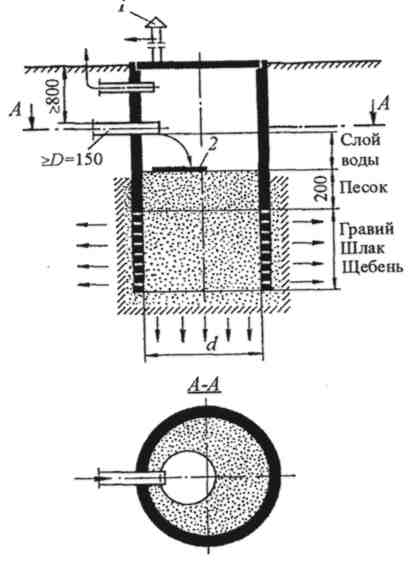
Индивидуальные очистные сооружения: К классу индивидуальных очистных сооружений относят сооружения, пропускная способность которых...

Семя – орган полового размножения и расселения растений: наружи у семян имеется плотный покров – кожура...
Индивидуальные очистные сооружения: К классу индивидуальных очистных сооружений относят сооружения, пропускная способность которых...
Семя – орган полового размножения и расселения растений: наружи у семян имеется плотный покров – кожура...
Топ:
Организация стока поверхностных вод: Наибольшее количество влаги на земном шаре испаряется с поверхности морей и океанов...
Методика измерений сопротивления растеканию тока анодного заземления: Анодный заземлитель (анод) – проводник, погруженный в электролитическую среду (грунт, раствор электролита) и подключенный к положительному...
Характеристика АТП и сварочно-жестяницкого участка: Транспорт в настоящее время является одной из важнейших отраслей народного...
Интересное:
Наиболее распространенные виды рака: Раковая опухоль — это самостоятельное новообразование, которое может возникнуть и от повышенного давления...
Отражение на счетах бухгалтерского учета процесса приобретения: Процесс заготовления представляет систему экономических событий, включающих приобретение организацией у поставщиков сырья...
Распространение рака на другие отдаленные от желудка органы: Характерных симптомов рака желудка не существует. Выраженные симптомы появляются, когда опухоль...
Дисциплины:
|
из
5.00
|
Заказать работу |
|
|
|
|
A self-routing ADC based on a neural network (SRADC NN) [2] (Fig. 1) has been chosen as a platform on whose basis the improvement of reliability indicators will be carried out. It makes possible to implement an ADC of a streaming dynamic architecture (SDA). ADC SDA have an undeniable advantage in that when measuring input signals, such devices can change the bit depth of the conversion, thus adjusting the processing speed of the input signal [3]. The ADC SDA also has the ability to measure several input signals simultaneously, using dedicated hardware resources, which allows optimizing the weight and size parameters and reducing the size of the device, and having a positive effect on the final cost.

Fig. 1. Block diagram of the SRADC NN. Ui is input analog voltages, ki is the required number of bits in the ADC to process the i-th input signal, Ni is the value of the sample obtained in the ADC for the i-th input signal, Ureference is the constant voltage used by the ADC to determine the weight coefficients of the bits
SRADC NN includes a block of comparators, a number of which is determined by the number of measured signals, a block for determining the required bit width and a neural network (Fig. 1) [2]. A neural network (NN) is a set of the same type of basic measuring neurons (BMN), each of which is a simple one-bit meter (element of the R-2R matrix), as well as a CS for this element. Moreover, BMN includes a signal routing system that allows combining BMN into an individual ADC (IADC) for a specific input signal with the required bit width [3]. Thus, the measurement is divided into 3 stages: IADC formation, measurement, IADC destruction. For the IADC formation, the "echo-location" method is used, which makes it possible to determine the state of the NN and find the required number of free SPEs [4]. The implementation of the "echo-location" method implies that the BMN in the NN are combined into a closed ring, to any part of which an input neuron can be connected (Fig. 2). To increase the fault tolerance of the entire system, additional connections between the BMN can be provided in the ring so that the IADC formation can be carried out avoiding the failed elements. This raises the question of how to determine the faulty SPE in the NN.
Figure 2. An example of a single-layer neural network with one input and output neurons and four SPEs in the hidden layer, with one additional connection between them.
One of the options for solving the problem with the search for failed BMN is the use of a self-testing system for each BMN [5], which is based on the fact that it analyzes the operation of the R-2R element CS and is triggered in the event of forbidden states, reveals all possible single constant defects in it. At the output of the self-testing system, a "readiness" flag is generated, which informs other related BMN that this element is operational and can participate in the IADC formation process. But at the same time, the system presented in [5] does not allow evaluating the operation of the R-2R element itself, which is very critical when making measurements, since the accuracy of the conversion depends on the values of the element resistance. Various calibration methods can be used to correct matrix errors to assess the adequacy of metrological performance.
|
|
In [6], a background calibration method using NN was proposed. The ADC consists of the main ADC (MADC), the reference ADC (RADC) and the NS. The MADC has a higher frequency, but less accuracy relative to the RADC. During its operation, a comparison is made every few clock cycles, and if the mismatch norm is exceeded, the weights are calibrated in the neural network. This method has the advantage of adapting to the gradually degrading hardware part of the MADC, but it does not save users from the degradation of the hardware part of the RADC, not to mention the complete failure of the hardware part of the RADC.
In [7], a calibration method is considered, which implies the presence of correction capacities. They change the "weight" of an element of the R-2R matrix when it deviates from the set value due to aging of the elements. This method is more accurate, but requires a sufficiently large number of additional elements.
Summarizing the principles of the two above-mentioned methods of calibration and the advantages of the SRADC NS, it is proposed: within the framework of one measurement, form three IADCs from a quasi-chaotic set of free BMNs, which will provide a majority system for determining hardware and metrological failures; the majority approach is applied at the BMN level, which are responsible for the same bits. If a mismatch is detected in the diagnostic process, the weight of the selected BMN is corrected by a given value. When the integral value of the correction exceeds the threshold value, then this BMN generates a fault flag.
Thus, a system with an increased level of reliability is obtained, which allows not only identifying a failure, but also adapting to it by means of calibration or disconnection of faulty BMNs. The advantage is that IADCs are formed from different sets of BMNs, which actually excludes situations in which 2 faulty BMNs "turn off" one operable BMN. The disadvantage is the need to have a larger number of SPEs to be able to form majority IADCs.
Conclusion
At the moment, it is necessary to select the most optimal calibration method taking into account the features of the SRADC NN. For this it is proposed to implement models for various presented methods and use them to estimate the most important parameters for the SRADC NN implementation:
• Hardware costs for the implementation of additional monitoring and diagnostic systems within each BMN in relation to the total number of elements required to implement the remaining BMN functions in the NN;
• Time spent on evaluating and correcting the IADC operation in conditions of parallel measurement of input signals with the ability to change the measurement bit depth;
• The number of additional connections between the BMN, or between the BMN and I/O neurons for the implementation of diagnostic systems.
It is important to follow the principles inherent in the algorithm for self-routing of signals within the neural network, which make it possible to abandon the central CS when developing the SRADC NN. Duplication of all control elements in each BMN is not desirable; instead, a local system must be used. In this case, each BMN will have a part of the control system, and the system as a whole will work when a certain number of BMNs are combined.
|
|
Thus, in the future, we can single out the following goals and objectives:
• Development of functional models of the diagnostic system for various calibration methods, taking into account the above requirements;
• Comparison and evaluation of the obtained models in order to identify the optimal method and the implementation of such a method in the form of a physical model;
• Correction of algorithms and models proposed by A.A. Eltyshev, A.I. Posyagin and A.A. Yuzhakov for calculating hardware costs and the number of BMN, taking into account an additional diagnostic system;
• Implementation of the SRADC NN with a diagnostic system and comparison of its characteristics with the ADC SDA used at the moment for the GTE parameters measurement.
Reference list
1. Титце, У. Полупроводниковая схемотехника. Том 2 / У. Титце, К. Шенк. – 12-е изд. – Москва : ДМК Пресс, 2007. – 942 с. : ил.
2. Посягин, А. И. Самомаршрутизация сигналов в аналого-цифровом преобразователе на основе нейронной сети / А. И. Посягин, А. А. Южаков // Известия высших учебных заведений. Приборостроение. 2014. Т. 57, № 5. С. 38–43.
3. Матушкин, Н. Н. Измерительные преобразователи на основе потоковой динамической архитектуры / Н. Н. Матушкин, А. А. Южаков // Известия высших учебных заведений. Приборостроение. 1994. № 1. С.16–21.
4. Макагонов, Н. Г. Принципы самомаршрутизации сигналов в аналого-цифровом преобразователе на основе однослойной нейронной сети / Н. Г. Макагонов, А. И. Посягин, А. А. Южаков // Электротехника. 2016. № 11. С. 3–6.
5. Кацко, Е. В. Диагностика в аналого-цифровом преобразователе на основе нейронной сети / Е. В. Кацко, А. И. Посягин // Прикладная математика, механика и процессы управления. 2013. Т. 1. С. 295–303.
6. Honghui, D. An efficient background calibration technique for analog-to-digital converters based on neural network / Deng Honghui, Hu Yijun, Wang Liang // Integration. 2020. V. 74. Р. 63–70.
7. Guan, R. A low-cost digital-domain foreground calibration for high resolution SAR ADCs / Rui Guan, Jing Jin, Jianjun Zhou // Microelectronics Journal. 2018. № 73. P. 86–93.
| Ilya Naborshchikov | Илья Наборщиков |
| Perm National Research Polytechnic University | Пермский Национальный Исследовательский Политехнический Университет |
| Solution of the multicriteria problem of optimizing fuel spillage in the fuel distribution system of a gas-turbine engine | Решение проблемы множественных критериев оптимизации разлива топлива в системе распределения топлива газотурбинного двигателя |
| Abstract: The mathematical formulation of a multicriteria problem of optimizing fuel spillage of the fuel distribution system (FDS) of a gas-turbine engine (GTE) is presented. A method for solving the optimization problem is described. The results of computational simulation of the FDS GTE with the parameters found in the optimization problem are presented. | Аннотация: Представлена математическая формулировка задачи с несколькими критериями оптимизации разлива топлива в системе распределения топлива (СРТ) газотурбинного двигателя (ГТД). Описан способ решения задачи оптимизации. Представлены результаты вычислительного моделирования СРТ ГТД с параметрами, найденными в задаче оптимизации. |
Keywords: optimization, fuel distribution system, gas-turbine engine, computational simulation.
|
|
1. Introduction
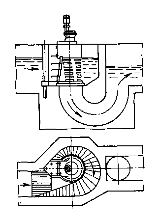
One of the most important tasks of modern aircraft engine building is to ensure sequential operation of all GTE components to eliminate non coincidence that can lead to unplanned fuel leaks from the hydraulic unit under consideration. Eliminating unplanned spillage and increasing the efficiency of fuel distribution can lead to improved performance of GTE, while reducing harmful emissions into the atmosphere and reducing resource costs during operation. The obtained results of numerical modeling will be taken into account in the development of the FDS GTE system.
FDS is designed for: supplying fuel to the combustion chamber (CC); fuel supply to hydraulic cylinders of GTE mechanization control [1]. The FDS includes: a locking valve (LV); purge air valve (PAV); distribution valve (DV); solenoid-operated valve; air inlet valve. Consider the modes of operation ART:
¾ Engine start mode: as the pump drive speed increases, the pressure in the GTE fuel system increases. Under the influence of fuel pressure, the movable elements of the units are set to the operating position, and fuel is supplied to the CC and to the actuators of the automatic control system (ACS) to implement the specified control programs [1].
¾ Engine stop mode: the fuel consumption in the CC decreases, the transition of the main mode to idling is performed. Then the LV cuts off the fuel supply to the CC and the fuel from the CC manifolds is drained into the vent tank. The collectors are purged with air from the PAV. In case of emergency shutdown, the fuel supply to the CC is stopped from any mode, and the fuel from the manifolds is drained into the vent tank [1].
¾ Engine main mode: DV distributes the working fuel along the CC through LV by changing the area of passage of the circuit openings by the spool depending on the value of the supplied working fuel consumption rate.
For the described FDS GTE, a numerical model was developed that consists of DV, LV and PAV. The construction of a numerical model was carried out in the MATLAB\Simulink software package. The model was developed for carrying out a number of numerical experiments in order to obtain fuel consumption characteristics and check the sequence of opening/closing LV and PAV at different engine operating modes. As a result of the numerical simulation of the FDS operation, an incorrect sequence of opening / closing LV and PAV was revealed, due to which the working fuel supplied from DV to LV began to penetrate through the PAV into the opening of the drainage system. This process, identified during the simulation, is fuel leaks from the FDS system.
In the course of studying the problems associated with fuel leaks, it was decided to pose and solve the multi-criteria problem of optimizing spillage.
2. Multicriteria problem of optimizing fuel spillage
We accept the hypothesis that variations in some parameters of the LV spring can affect the change in leakage, namely, the change in the parameter of the stiffness coefficient  and initial deformation of the spring
  . The mathematical formulation of the multicriteria spillage optimization problem will look like:
|
|

The domain of definition of the parameters and are conditions (1) and (2) respectively. Equation (3) calculates the volume of fuel supplied to the system for the time interval [  ]. Equation (4) calculates the volume of leaks over the time interval [
  ]. Conditions (6) – (8) impose restrictions on the force of the spring acting on the spool, this force cannot be: less than the initial force of the spring; more than the sum of opposing forces; more than fuel pressure. Conditions (9) and (10) impose restrictions on the permissible difference between the opening/closing times of PAV and LV.
The solution to the multicriteria leak optimization problem will be based on the direct search method [2]. Let’s define a coordinate plane, where on the x-axis we define  , nd on the y-axis we define
  . Divide the resulting coordinate system into n equal parts along the x and y axes, we obtain a step:
 , (11)
 , (12)
In total, the coordinate plane will be split into  points. For each point
  ,
,  с with a fixed step
  along the x-axis and a fixed step
  along the y-axis, the system (1) – (10). As a result, a point will be found that best meets all the constraints of this system.
In equations (1) - (12), the following designations are adopted:
– initial spring deformation; – the stiffness coefficient;  – the moment of the beginning of the LV opening;
  – PAV closing moment;
  – LV closing moment;
  – the moment of the beginning of the PAV opening;
  – time difference between and at system start;
  – me the difference between and when the system is turned off;
  – value of the integral value of fuel leakage;
  – value of the integral value of fuel consumption in GTE;
  – fuel consumption function obtained from the numerical model FDS;
  – fuel leakage function obtained from the numerical model FDS;
  spring force acting on the spool;
  – initial spring force acting on the spool;
  – influence of other forces on the spool;
  – fuel pressure; a,b,c,d,m,j – variable parameters of the model; – fixed x-axis pitch; – fixed y-axis pitch;
  – step number.
Conclusion
As a result of solving the multicriteria optimization problem, a graph was obtained for the volume of fuel leaks at points (x, y).
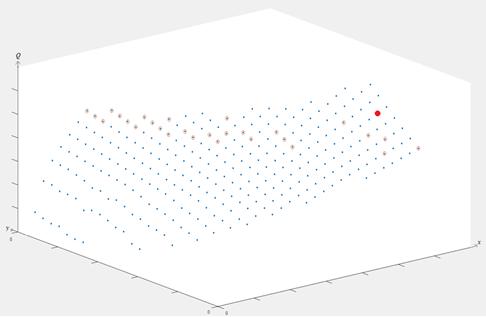
Figure 1. The graph of the volume of fuel leaks Q depending on the choice of points on the x and y axes
Points that satisfy constraints (6) – (8) are marked with a blue marker. Blue markers outlined in red indicate points that satisfy constraints (6) - (10). The red marker indicates the point that is the best among all found.
During the numerical simulation of the FDS with the found characteristics of the spring in the course of solving the multicriteria optimization problem, the results were obtained at which:
¾ Managed to eliminate the time difference between LV opening and PAV closing, at the start;
¾ It was possible to reduce by 2 times the difference in time between LV closing and PAV opening, when switching off;
¾ Managed to reduce the volume of fuel leaks from the FDS by 3 times;
¾ It was possible to keep the original fuel consumption value in GTE.
Reference list
1. Иноземцев, А. А. Газотурбинные двигатели / А. А. Иноземцев, В. Л. Сандрацкий. – Пермь : ОАО «Авиадвигатель», 2006. – 1204 с.
2. Васильев, Ф. П. Методы оптимизаций / Ф. П. Васильев. – Москва : Факториал Пресс, 2002. – 823 c. – ISBN 5-88688-056-9.
3. Ивченко, Г. И. Введение в математическую статистику : учебник / Г. И. Ивченко, И. Ю. Медведев. – Москва : ЛКИ, 2010. – 600 с.
4. Калинина, В. Н. Математическая статистика : учебник / В. Н. Калинина, В. Ф. Панкин. – 4-е изд., испр. – Москва : Дрофа, 2002. – 336 с. : ил. – ISBN 5-7107-6039-0.
| Alexandr Nikiforov | Александр Никифоров |
| Perm National Research Polytechnic University | Пермский Национальный Исследовательский Политехнический Университет |
| Identification of Mechanical Behavior Features of Polymer Composite Samples when Embedding Smart layers with Fiber-optic Sensors | Идентификация механических поведенческих особенностей полимерных композитных образцов при встраивании смарт-слоёв с помощью волоконно-оптических датчиков |
| Abstract: The paper discusses the issue associated with identifying the features of the mechanical behavior of samples from polymer composite materials when embedding various Smart layers. Two technologies for producing Smart layers are considered: fusion of thermoplastic films and 3D-printing. Quasi-static tests of samples with embedded Smart layers made using the film fusion technology and uniaxial loading tests of samples with mounted Smart layers made by 3D printing are carried out. The advantages and disadvantages of Smart layers made using different technologies are described. Objectives for further research are given. | Аннотация: В работе обсуждается вопрос, связанный с выявлением характеристик механического поведения образцов из полимерных композиционных материалов при встраивании различных смарт-слоёв. Рассматриваются две технологии получения смарт-слоёв: слияние термопластических пленок и 3D-печать. Проводятся квазистатические испытания образцов со встроенными смарт-слоями, выполненные с использованием технологии плавления пленки, и одноосевые испытания образцов с установленными смарт-слоями, выполненные 3D-печатью. Описываются преимущества и недостатки интеллектуальных слоев, созданных с использованием различных технологий. В нем излагаются цели дальнейших исследований. |
Keywords: Fiber Optic Sensor (FOS), Smart-layer, 3D-printing, fusion of thermoplastic films, Structural Health Monitoring.
|
|
Introduction
At present, special attention must be paid to changing the physical and mechanical characteristics (strength and stiffness) of different-purpose structures (used in aviation, aerospace industries, etc.), which, as a rule, experience a complex non-homogeneous stress-strain state. In this regard, it is relevant to use the so-called Structural Health Monitoring Systems (SHMS) [1-3].
Structural Health Monitoring Systems are most popular for recording in real time the changes in temperature and deformation fields, areas of defect localization, which leads to structural damage [4]. In the majority of existing systems for monitoring technical condition, fiber-optic sensors (FOS) are used as sensors having several advantages: small size, high sensitivity, resistance to electromagnetic fields, the ability to be combined into a single network with other sensors, a wide range of measured values.
Fiber optic sensors in such monitoring systems can be embedded or mounted on the surface of the structure under study. During the mounting process FOSs are glued with different adhesive compositions. In this case, it is necessary to provide a hard FOS-structure interface, which is difficult when conducting field testing of various structures. Another problem is the impossibility of disconnecting the FOS from the structure without damaging the fiber lines.
The FOS embedding in the material is possible, as a rule, only in a structure made of composite materials (CM). However, with the direct embedding of the sensors in such a structure a number of problems appear:
· the complexity of the sensor embedding at the stage of structure production due to the fragility of the fiber, i.e., fiber lines can disintegrate in the structure itself or at the exit from the PCM structure during the thermoforming process,
· the complexity of the sensing element location, i.e. sensors can “float away” during the thermoforming of PCM structures when the resin moves, thereby the monitoring area changes.
In addressing the issues described above, Acellent Technologies, Inc. developed a Smart-layer which allows protecting sensors of various types (fiber-optic, piezoelectric sensors) and their outputs to ensure the accuracy of the sensing element in the monitoring area [5]. In [6], that company described their own technology for creating the Smart Layer, in which a network of piezoelectric sensors was placed between a polyimide film and coated with epoxy resin. This technology of creation enables ensuring the integrity of the sensors. It can be used for surface monitoring of structures, but it cannot be used for embedding sensors directly into PCM structures since polyimide films have poor adhesion to carbon fiber reinforced polymers
(CFRP). The thickness of such a layer reaches 2-4 mm, which can significantly affect the physical and mechanical characteristics (PMCs) of such structures.
Thus, the purpose of the study is to develop a Smart-layer that protects the FOS during the production of PCM structures and during surface monitoring, which will not significantly affect the PMCs of PCM structures.
Materials and methods
For a Smart layer making, it is advisable to state a number of requirements for materials that will correspond to the features of technologies for manufacturing products from polymer composite materials:
1) the material of the Smart-layer should not yield at the temperatures of PCM samples and structures formation (180° C);
2) the material of the Smart-layer must completely protect the fiber-optic line both when embedding a PCM element into the structure, and under surface placing of the sensing elements.
3) when surface placing, the Smart-layer must be flexible and elastic to accept any geometry of the element being diagnosed, and also to protect sensitive elements against mechanical damage and external influences;
4) The Smart-layer should not have a significant effect on the PMCs, when embedded into the structure of a polymer composite material.
5) The Smart layer must fully transfer the load perceived by the structure to the sensitive elements in the fiber-optic line;
6) The Smart layer should not distort the signal arriving at the sensing elements in the fiber-optic line.
For the successful application of the Smart-layer, it is necessary to meet all the requirements which must be considered in conjunction and in a clear sequence.
In this study, two manufacturing technologies were considered, namely, fusion of various thermoplastic films and 3D printing of the layer as an integral part.
Results and discussion
At the first stage of the study, such materials, as thermoplastic polyurethane, polyamide and polymer reinforced mesh, were used for the layer production. To imbed fiber-optic lines in polymer films and make a Smart layer, technological equipment for polymer films fusion and FOS fixing in the required places was designed. In the course of the study, prototypes of Smart layers with a thickness of 0.3 mm were made, which were later embedded into PCM samples for mechanical testing on tension, compression, and interlayer shear. According to the results of mechanical tests, the following conclusions were made:
- the lowest PMC reduction was observed in the samples with an embedded Smart layer based on polyamide (about 10%) compared to the reference samples.
- the developed prototypes were able to protect the FOSs during the sample forming process;
- all the Smart layer prototypes fully transmit the load and do not distort the signal.
Thus, all the developed prototypes allow us to mark the changes in temperature and strain fields in real time.
However, it should be noted that the Smart layer technology based on the polymer film fusion process has a significant drawback at this stage. That is, an optical fiber is displaced relative to the centre of the layer, which occurs due to insufficient tension and fixation of the fiber during the layer formation. Insufficient fiber tension and its fixation in tooling contribute to the longitudinal displacement of the fiber during the melt movement when the layer is formed, which leads to the wave-like deformation of the optical fiber. Based on the results obtained, it was decided to consider 3D printing technologies for the production of Smart layers in order to solve the problem of FOS placing.
At the second stage of the study, structural high-temperature plastics, namely polyamide, polyamide reinforced with carbon fibers and ABS+, were used as materials for the production of Smart layers. In the process of testing the 3D printing technology, a three-dimensional Smart layer model was developed, and various temperature and speed ranges of printing were considered. As part of the study, it was found that the minimum thickness of the Smart layer made using 3D printing technology was 1 mm, which significantly exceeded the thickness of the layer made using polymer film fusion technology. When performing the sample loading tests with mounted Smart layers, it was found that the deformations were transmitted completely, and the signal was not distorted.
Conclusion
Thus, in this study, two technologies for production of Smart layers were considered: 3D printing and fusion of polymer films. Based on the results obtained, it was found that smart layers made by the 3D printing technology had a smaller thickness, did not distort the original signal, and demonstrated an insignificant decrease in PMC when they were embedded into the PCM samples. 3D printed smart layers were 1mm thick. However, when making layers by the 3D printing technology, an optical fiber was not displaced from the original location. Hence, the FOSs allow monitoring the structural state of the system in the observed area under the surface mounting.
The next stage of the study was the embedding of the Smart layers made by the 3D printing technologies into the PCM samples in order to display the PMC decrease and the possibility of their further use for embedding into laminated structures.
Acknowledgments
The results were obtained during the fulfillment of the state task of the Ministry of Science and Higher Education of the Russian Federation for the implementation of fundamental scientific research (project No. FSNM-2020-0026).
Reference list
1. Gholizadeh, S. A review of non-destructive testing methods of composite materials / S. Gholizadeh // Procedia Structural Integrity. 2016. V. 1. P. 50–57.
2. Fan, Y. Characterization of a FBG strain gage array embedded in composite structure / Y. Fan, M. Kahrizi // Sensors and Actuators A: Physical. 2005. V. 121, №. 2. P. 297–305.
3. Farrar, C. R. An introduction to structural health monitoring / C. R. Farrar, K. Worden. – DOI 10.1098/rsta.2006.1928. – Text : electronic // Scribd : [site]. – URL: https://ru.scribd.com/document/444132984/An-introduction-to-structural-health-monitoring (date accessed: 17.02.2021).
4. Sante, R. Fibre Optic Sensors for Structural Health Monitoring of Aircraft Composite Structures: Recent Advances and Applications / Raffaella di Sante. – DOI 10.3390 /s150818666. – Text : electronic // Semantic Scholar : [site]. – URL: https://pdfs.semanticscholar.org/578f/87dc8f5f17c7e8368b4381807eed66d4f5ea.pdf?_ga=2.140537010.1669056146.1624946814-1205810423.1624946814 (date accessed: 26.02.2021).
5. Advances in the development of built-in diagnostic system for filament wound composite structures / X. P. Qing, S. J. Beard, Amrita Kumar [et al.] // Composites Science and Technology. 2006. V. 66. P. 1694–1702.
6. A hybrid piezoelectric/fiber optic diagnostic system for structural health monitoring / X. Qing, A. Kumar, Z. Chang [et al.]. – DOI 10.1088/0964-1726/14/3/012 // ResearchGate : [site]. – URL: https://iopscience.iop.org/article/10.1088/0964-1726/14/3/012 (date accessed: 26.02.2021).
| Danil Orekhov | Данил Орехов |
| Perm National Research Polytechnic University | Пермский Национальный Исследовательский Политехнический Университет |
| Determing a rational construction design for a double-fired solid propellant rocket motor | Отказ от рациональной конструкции твердотопливного ракетного двигателя |
| Abstract: reasons for determining a rational construction design of a solid propellant rocket motor (SRM) with a thrust control over time are suggested in the paper. Based on the results of design calculations, the comparative analysis of construction designs was carried out, using the objective parameters and expert assessment. Ways to optimize the design of a double-fired SRM are proposed. | Аннотация: В работе предлагаются основания для определения рациональной конструкции твердотопливного ракетного двигателя (ТРД) с временным управлением тягой. На основе результатов проектных расчетов был проведен сравнительный анализ строительных проектов с использованием объективных параметров и экспертной оценки. Предложены способы оптимизации конструкции двухтопливного ТРД. |
Keywords: thrust vector control over time, rocket motor, double-fired solid propellant rocket motor, efficiency indicator, comparative analysis.
Introduction
Over the past few decades, ever higher requirements have been imposed on aerodynamic rockets (anti-aircraft, aviation, anti-tank, etc.). Previously, it was believed that the range of rockets of this class depended to a great extent on a rocket power-to-weight ratio. Therefore, acceleration to the required speed at the end of the trajectory active section was sufficient to provide the required ballistic characteristics. Design mass, overall dimensions and energy characteristics were the underlying efficiency factors. However, to date, extending the flight range of aerodynamic rockets by improving their energy supply has a number of difficulties [1]. This is due to design, size and technological constraints imposed on the rocket design in general and on the motor in particular.
Energy use as a determining factor in extending the flight range of an aerodynamic rocket is only valid for small fuel reserves. As the fuel supply increases  , the impact of the thrust program on the rocket characteristics increases dramatically. It is believed that SRM with a variable thrust program in terms of operating time makes it possible to significantly extend the flight range of the «air-air» class rockets under different conditions by 15% compared to a single-fired propellant rocket [2].
It is known that thrust control in SRM over time is only possible for a certain number of times since the combustion process cannot be stopped. This allows us to assume that the number of SRM operating modes should be based on ballistics and rocket tactics.
Thus, the study aims at determining the rational design of SRM with the control of thrust over time. To achieve this aim the following objectives should be accomplished:
· Formulating criteria to assess the construction design effectiveness;
· Carrying out design calculations;
· Assessment of advantages, disadvantages and features of the construction designs under consideration;
· Formulating recommendations to optimize SRM.
Method
1. To select from all the available motor construction designs that allow controlling thrust over time, the criteria to be met by the options under consideration were formulated:
- Two-chamber motor with inclined nozzles;
- Two-chamber motor with central gas duct;
- Two-chamber motor with intermediate nozzle;
- Single-chamber motor with intermediate bottom;
- Single-chamber motor with diaphragm seal unit;
- Single-chamber motor with end-combustion charge;
- Single-chamber motor with elastic dividing shell;
- Single-chamber motor with non-force partition and heat filter.
These criteria were determined to assess effectiveness of the selected construction designs. They are presented in table 1.
Table 1. Criteria for assessment of a construction design effectiveness
| Criteria |
| SRM is fired two times |
| There may be a pause between operating modes |
| Requirements for energy parameters of the 1st and 2nd operating modes are different. |
2. To study each of the selected construction designs according to the determined criteria, in-ballistic, gas-dynamic, thermal and strength calculations were carried out.
Based on the criteria given in Table 1, the following construction designs were selected as desired: single-chamber motor with intermediate bottom (Fig.1), single-chamber motor with diaphragm seal (Fig.2) and single-chamber motor with end-combustion charge (Fig.3).

Figure 1 Single chamber motor with intermediate bottom

Fig. 2 Single chamber motor with diaphragm seal

Fig. 3 Single chamber motor with end-combustion charg
3. To determine the optimal construction design for further study the comparative analysis of the selected designs was made in terms of their advantages and disadvantages (see Table 2).
Table2. Advantages and disadvantages of the construction designs under consideration
| Single chamber motor with end-firing charge and intermediate bottom | Single chamber motor with diaphragm seal | Single chamber motor with intermediate bottom |
| Advantages: Best Mass Perfection Ratio; Simulation of intra-chamber processes; Significant mass gain for the 2nd mode CS compared to the 1st mode CS. | Advantages: Mass gain in separating diaphragm compared to intermediate bottom; High simulability and predictability of intra-chamber processes after membrane opening. | Advantages: Good performance for mass excellence; No questions on filling in CS of the 1st and 2nd operating modes. |
| Disadvantages: No clear understanding of intra-chamber processes due to the small volume of analog products; Difficulties in mode 1 charging technology. | Disadvantages: Large mass of structure as a whole; No clear understanding of how the membrane will open and what will happen in CS at this moment. | Disadvantages: Design is less advanced than end-combustion charge; Other disadvantages are similar to a single-chamber motor with end-combustion charge. |
4. Finally, an expert assessment of the selected construction designs was made on the basis of comparative analysis to determine the optimal construction design. In this assessment, the following factors were taken into account: “construction mass - to - propellant mass” ratio, manufacturability, need to validate the solutions, risk of failure.
Results and Discussion
The results of expert assessment made for the selected construction designs are presented in Table 3.
Table3. Expert assessment of the selected construction designs
| № | Evaluation category | Intermediate bottom | With separating diaphragm | |
| With a charge of end combustion | With a channel charge in both modes | |||
| 1 | “Construction mass- to-propellant mass” ratio | 0,58 | 0,62 | 0,65 |
| 2 | Manufacturability | Medium | High | Below average |
| 3 | Need for experimental approval | High | Above Medium | Very high |
| 4 | Failure probability | Unlikely to happen | Unlikely to happen | More likely to happen |
On the one hand, the design made with the use of a separating diaphragm has a smaller mass and seems to be lighter. But on the other hand, as a whole it involves a larger number of additional structural elements which make the motor more complex. So, the construction mass increases as compared to that of the motor construction design with intermediate bottom.
It is also not clear how a non-metallic diaphragm will behave when the second-mode charge is ignited and burned.
As for the design with an intermediate bottom it turned out to be optimal. This solution allows us to obtain the most acceptable characteristics with predictability of intra-chamber processes.
However, there is no good experience of working with such construction designs. Another disadvantage of this solution is due to a number of design-related technological features.
Conclusion
The study provides the practical procedure of determining the optimal motor construction design required for further research of intra-chamber processes.
Further improvement and optimization of SRM construction design is viewed in terms of its mass/weight and implies the following steps:
· Application of composite materials in a hull construction;
· Solution of optimization problem related to gas dynamics, thermal stability and construction strength of the hull and intermediate bottom as an "inseparably connected" structural element;
· Application of topological optimization technology in combination with additive technologies.
Reference list
1. Solid Fueled ramjets and Ducked Rockets (Theory and Designing) / V. N. Aleksandrov, V. M. Bitskevich, V. K. Verkholmov [et al.] ; editor: L. S. Yanovsky. – Moscow : Academbook, 2006. – 311 p.
2. Управляемые энергетические установки на твердом ракетном топливе / под общ. ред. М. И. Соколовского, В. И. Петренко. – Москва : Машиностроние, 2003. – 464 с. : ил. – ISBN 5217031239.
| Irina Peretrukhina | Ирина Перетрухина |
| Perm National Research Polytechnic University | Пермский Национальный Исследовательский Политехнический Университет |
| Study of channel roughness reduction in a silica glass preform | Изучение методов снижения шероховатости каналов в предварительной форме силикатного стекла |
| Abstract: This paper deals with the problem of reducing the roughness of the inner surface of drilled channels in silica glass preform during the optical fiber production. It is assumed that the reduction in surface roughness depends on the choice of drilling modes and the grain size of the drills used. | Аннотация: В данной работе рассматривается проблема снижения шероховатости внутренней поверхности буровых каналов в предварительной форме силикатного стекла при производстве оптического волокна. Предполагается, что снижение шероховатости поверхности зависит от выбора режимов бурения и размера гранул используемых буровых установок. |
Key words: anisotropic fiber (waveguide), drilling, optical fiber, preform, silica glass
Introduction
Silica glass preform is the main thing from which optical fiber is obtained. It is used as one of the main components of a fiber optic gyroscope. In Russia, in spite of the fact that the production process of both is well-established, there are technological difficulties, considered by many researchers and engineers. One of these problems is the production of longitudinal symmetric channels in a cylindrical preform.
There are two main methods for obtaining such channels. One of them through chemical etching is described in A. M. Kurbatov's patent [4]. This method is complex, difficult to control, time consuming, but relatively inexpensive.
The other method is classical [2], used by foreign companies for the optical fiber production. It is the formation of channels by drilling silica glass. This method is simple to execute, easy to control, short in time, but expensive for a domestic manufacturer.
The high cost of the second method is due to the lack of Russian specialized equipment for drilling channels, which demands to purchase foreign machine tools and drills. But this method is still cost-effective for the optical fiber production. Therefore, it is used at Russian enterprises.
The use of imported equipment does not guarantee the quality of the preforms obtained. Their quality is provided by the manufacturing technology. So far there has been no technology for polishing the inner surface of channels in a silica glass preform. Damage left by the drill can later appear as air voids, which will greatly affect the optical properties of the fiber. Therefore, the formation of channels dictates the need to reduce the roughness of the drilled surface of the channels.
The purpose of the work was to select a mode for drilling the channels of anisotropic fiber preforms to eliminate the formation of air voids when the preform is fused with loading rods filling the channels.
|
|
|
Состав сооружений: решетки и песколовки: Решетки – это первое устройство в схеме очистных сооружений. Они представляют...
Типы оградительных сооружений в морском порту: По расположению оградительных сооружений в плане различают волноломы, обе оконечности...

Наброски и зарисовки растений, плодов, цветов: Освоить конструктивное построение структуры дерева через зарисовки отдельных деревьев, группы деревьев...
Механическое удерживание земляных масс: Механическое удерживание земляных масс на склоне обеспечивают контрфорсными сооружениями различных конструкций...
© cyberpedia.su 2017-2024 - Не является автором материалов. Исключительное право сохранено за автором текста.
Если вы не хотите, чтобы данный материал был у нас на сайте, перейдите по ссылке: Нарушение авторских прав. Мы поможем в написании вашей работы!