All treatment methods can be categorized by the physical principles.
Thermal surface treatment. On a material surface, the energy flux, which causes fast surface heating and, as a consequence, its melting, is oriented. After that, the part being treated is cooled to trigger the recrystallization process and to form the fine grained structure. Surface heating can be performed by three methods: laser surface treatment, induction surface hardening and electropulsing surface treatment.
In the first case, surface is heated by the directed light flow beam which generates three microstructure regions in thickness. The initial one features disturbed homogeneity grains with a mean size of a few hundred nanometers. In the second region, the irregular shaped grains with a heterogeneous distribution in thickness are observed. The third region is an area of the undeformed grains. For Zr702, the surface layer depth equals about 350 µm and the surface hardness is raised by a factor of 1,75.
In the second case, a part is placed in a variable magnetic field, which initiates the return electrical vortex currents, heating the part, on its surface. The grain structure changing in thickness is similar to the first technical operation. For AMS6414, the surface layer depth is approximately 800 µm and the surface hardness is enhanced 1.75 times [1]. Electropulsing surface treatment is a similar treatment method, with difference in electric currents to be provided by the galvanic connection.
Thermochemical surface treatment. A machine part is put in a saturating environment at increased temperature. Nitrogen (nitriding), chromium (chromizing), carbon (carburizing), etc can be applied as saturating particles. With time, environment particles penetrate to the part, which induces microstructure changes, including phase and chemical composition alteration. The diffusion mechanisms, which are accelerated when the phase transition emerges and strongly depend on the structure granularity (the higher a grain size, the slower diffusion), are responsible for velocity and depth permeation. The appearing concentration gradient of diffusible particles creates the microhardness gradient and the residual strains. It produces the negative tangential residual stress field positively affecting the strength.
Saturating environment can be gaseous, liquid, plasma or solid. The last one is more rarely employed than other treatment types because it is not enough effective and requires a necessary gap between saturating solid environment and a part, in which a gaseous phase is formed. The comparison of nitriding methods for AISI H13, AISI P20 and N8550 materials by the case depth and the extent of hardness enhancement (the hardness ratio - HR) is demonstrated in Table 1 [2].
Table 1. Efficiency of different nitriding types
| Material
| Gas Nitriding
| Plasma Nitriding
| Solid Nitriding
|
| Depth, µm
| HR
| Depth, µm
| HR
| Depth, µm
| HR
|
| AISI H13
| >140
| 828/300
| 100
| 723/
| 47
| 723/
|
| AISI P20
| >140
| 900/550
| 66
| 1050
| 11
| 600
|
| N8550
| >140
| 1000/500
| 67
| 650
| 92
| 800
|
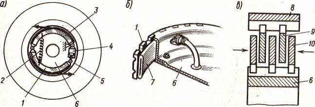
Mechanical surface treatment. A mechanical force impacts a sample surface, which initiates the plastic strains of the layer and, as a result, augments microhardness. Furthermore, surface plastic strain heterogeneity changing in thickness causes the negative tangential residual stress field. As a rule, this treatment is carried out by a shock pulse sequence, during which the surface achieves a limit of plastic strain saturation. After it is attained, the surface strengthening turns out not effective. It demands the selection of optimal number pulses influencing one spot. A mechanical impact is realized by one of the three technical operations: shot peening, ultrasonic surface treatment and laser shock peening.
In the course of shot peening, an air flux, mixed with high energy abrasive particles of a little spherical shape, is fed on a sample. Size and material of the particles are chosen in accordance with the processing material. This kind of treatment provides a relatively weak plastic layer depth. For instance, the plastic layer depth of AISI 304 is 150 µm and maximal hardness enhances around 2.25 times.
Ultrasonic surface treatment is fulfilled by an indenter created from a harder material than the specimen, which impacts the surface at a right angle. The indenter’s oscillative movement occurs in the range from 10 to 50 kHz. Generally, the indenter head has spherical shape and its size relies on a processing material. For the titan alloy VT1, the strengthened layer penetration depth equals 100 µm while the maximum hardness after the treatment increases 1.48 times. In the case of VT6, the observed case depth amounts to 60 µm and the surface microhardness augments 1.15 times after the processing. A significant difference in the hardening method efficiency for these alloys is due to considerably higher hardness of VT6 in comparison with VT1 (1.64 times) [3].
One of the progressive mechanical method treatments is the laser shock peening. Two layers are placed sequentially on a part. The first layer connected with the sample absorbs the laser radiation. The second one is transparent for the radiation. The energy flux evaporates the first coat, turning it into a gas, but, on the other hand, the second layer prevents gas movement from the sample, therefore, a shock pulse influencing on it is generated. Radiation power, its frequency and time are the controlled variables, from which total strengthening depends. Processing of aluminum alloy Al-6061-T6 by a low energy laser (300 mJ) gives the case depth about 1.5 mm while the extent of maximum hardness increase equals 1.2 [4].
Coupled Surface Treatment Methods
A further surface property improvement can be accomplished by a combination of basic surface treatment methods. Three types of these couplings are singled out.
Electropulsing-ultrasonic surface treatment (EUST). A sample surface is processed consistently following the scheme: electropulsing  ultrasonic mechanical vibration electropulsing. In contrast to UST, for 45 steel treated with EUST a bigger surface layer depth is ensured, namely 0.5 mm against 0.3 mm, and the maximal microhardness proves slightly lower (340 HV against 360 HV) [5]. A strong difference is observed in the final microstructure. In EUST, electropulsing accelerates diffusion mechanisms, which leads to faster migration of grains or subgrains and greater grain refinement. Therefore, the total corrosion resistance of a EUST specimen will be dramatically higher.
Plasma Nitriding or Chromizing with Shot Peening (PNSP and PCSP). As mentioned above, atom diffusion on grain boundaries proceeds significantly faster than in a volume phase, hence the smaller a mean grain size, the quicker diffusion to flow. Beyond that, the high dislocation density accumulating the energy after SP speeds up the atom motion. Using those facts, it was proposed to process a sample surface by metallic balls at the beginning and afterwards to put the sample in the plasma nitriding or chromizing environment. It leads to a remarkable improvement of a treatment layer through a larger hardening phase numbers. In case of the stainless steel AISI 304, the maximal microhardness after PN is 600  , that is two times lower than after PNSP [6]. The pre-surface layer depth rises from 15 µm to 25 µm. For steel AISI H13, after PCSP the maximal hardness increases 1.36 times and the case depth - from 10 µm to 30 µm [7].
Laser Shock Peening with Ball Shot Peening (LSPBSP). At the start, a specimen is treated by LSP followed by MSP. For Ti-6Al-4V, compared to standard LSP this procedure gives rise to a 70 µm nanostructure layer with the deformation twinning and not 10 µm layer with nanoscale deformation twinning. It gives larger microhardness. In contrast to BSP, the negative residual stress deep is augmented from 250 µm to 2 mm and their maximum values do not virtually differ [8].
Conclusion
The paper reviewed the main surface strengthening methods, being implemented by thermal, thermochemical and mechanical processing. Among them, the most promising method is the laser shock peening providing the hardening layer depth up to 2 mm, whereas the rest approaches ensure, in the best case, a few hundred micrometers. Coupling of two technical operations results in better hardening. In particular, EUST application instead of the basic UST gives a larger case depth. The same effect is observed when PNSP and PCSP are employed as a substitute for the usual PN and PC. A common feature of samples subjected to the coupled treatment method is the considerable distinction between their surface microstructure and microstructure generated by using standard methods. The final volume and surface properties of a treated material (both mechanical and physical) strongly depend on the surface processing. Therefore, selection of an optimal method for a particular material requires extensive experimental and theoretical research and is not unambiguous.
Reference list
1. Measurement and correction of residual stress gradients in aeronautical gears after various induction surface hardening treatments / V. Savaria, H. Monajati, F. Bridier, P. Bocher // Journal of Materials Processing Technology 2015. V. 220. Р. 113–123.
2. Almeida De, E. A. D. S. Acquired properties comparison of solid nitriding, gas nitriding and plasma nitriding in tool steels / E. A. D. S. De Almeida, J. C. Giubilei Milan, C. Edil da Costa // Materials Research. 2015. № 18 (1). P. 27–35.
3. Ultrasonic surface treatment of titanium alloys. The submicrocrystalline state / V. A. Klimenov, V. A. Vlasov, V. Y. Borozna, A. A. Klopotov. – Text : electronic // ResearchGate : [site]. – URL: https://www.researchgate.net/publication/281787913_Ultrasonic_Surface_Treatment_of_Titanium_Alloys_The_Submicrocrystalline_State (date accessed: 01.03.2021).
4. Sathyajith, S. Effect of laser shot peening on precipitation hardened aluminum alloy 6061-T6 using low energy laser / S. Sathyajith, S. Kalainathan // Optics and Lasers in Engineering. 2012. № 50 (3). P. 345–348.
5. Effect of electropulsing-ultrasonic surface treatment on the surface properties and the corrosion behavior of 45 steel / B. Zhang, H. Wang, S. Zhang [et al.]. – Text : electronic // ResearchGate : [site]. – URL: https://www.researchgate.net/publication/303291608_Effect_of_electropulsing-ultrasonic_surface_treatment_on_the_surface_properties_and_the_corrosion_behavior_of_45_steel (date accessed: 05.03.2021).
6. Plasma nitriding of AISI 304 stainless steel: role of surface mechanical attrition treatment / T. Balusamy, T. S. N. Sankara Narayanan, K. Ravichandran [et al.] // Materials Characterization. 2013. V. 85. P. 38–47.
7. Lu, S. D. Enhanced chromizing kinetics of tool steel by means of surface mechanical attrition treatment / S. D. Lu, Z. B. Wang, K. Lu. – Text : electronic // ResearchGate : [site]. – URL:https://www.researchgate.net/publication/222658728_Enhanced_chromizing_kinetics_of_tool_steel_by_means_of_surface_mechanical_attrition_treatment (date accessed: 01.04.2021).
8. Microstructural characterization of metallic shot peened and laser shock peened Ti-6Al-4V / S. J. Laine, K. M. Knowles, P. J. Doorbar [et al.] // Acta Materialia. 2017. V. 123. P. 350–361.
| Vladlena Markvirer
Svetlana Ulitina
| Владлена Марквирер
Светлана Улитина
|
| Perm National Research Polytechnic University
| Пермский Национальный Исследовательский Политехнический Университет
|
| Video Stream Object Recognition Module for Intelligence Buildings
| Модуль распознавания объектов видеопотока для зданий разведки
|
| Abstract: The article presents analytical review of existed solutions and technologies applied in computer vision control access systems, video monitoring and analysis areas. Such technologies are parts of the smart city concept and commonly used for recognition of faces in modern office buildings and business centers. Face recognition is used to distinct employees and guests, separated rooms and to evaluate the position of people, to expose atypical behavior. Commercial centers use such technologies for storing marketing information and estimating more popular route of buyers’ movements. The article discusses the process of construction and realization of object recognition in video stream prototype system. This prototype uses single-board computer Raspberry Pi 3 model B+ and RPi-camera (Raspberry Pi Camera Board v2.1). Prototype can be used as the video recording module of “Smart office” or “Smart home” system
| В статье представлен аналитический обзор существующих решений и технологий, применяемых в системах доступа к управлению компьютерным зрением, в области видеонаблюдения и анализа. Такие технологии являются частью концепции разумного города и обычно используются для распознавания лиц в современных офисных зданиях и бизнес-центрах. Распознавание лиц используется для отдельных сотрудников и гостей, раздельных комнат и для оценки положения людей, для выявления нетипичного поведения. Коммерческие центры используют такие технологии для хранения маркетинговой информации и оценки более популярных маршрутов движения покупателей. В статье обсуждается процесс построения и реализации распознавания объектов в прототипной системе видеопотока. Прототип использует одноплатный компьютер Raspberry Pi 3 model B+ и RPi-камеру (Raspberry Pi Camera Board v2.1). Прототип может использоваться в качестве модуля видеозаписи системы "Smart office" или "Smart home"
|
Introduction
Nowadays lots of research and development works show that computer vision and object recognition technologies have become more demanded in the information technologies market and are commonly used in practice. Computer vision is used to solve different tasks from domestic up to industrial scale.
In casual life people use smartphones to communicate through social media services, to share their thoughts and stories with friends and relatives. The embedded camera and mobile applications are used in these processes. Users are excited of such features of photos as masks, transformations of face from an actual state to a childly or elderly, or even swapping of faces.
It is worth noting that technologies of augmented and virtual reality (AR and VR) are rapidly developing now. These technologies are used for adding objects and fixing them at some point of the real picture (AR) or ultimately change it (VR) in real time. However, it is not the subject of the article and it requires more detailed consideration.
The main idea of this article is video surveillance systems for recognition faces. Such systems are used for securing and observing surrounding territory and inside of houses or offices. Security surveillance systems assume the presence of the number of IP-cameras and controller in terms of user interface application that may send notifications to users to alert about dangerous situation or to inform about events. Often ready-made systems give us limited scope of functions and ability to extension. Sometimes security systems have functionality of recognition, but such systems are more expensive than surveillance systems itself [1].
In industrial sphere organizations use systems to ensure security by using turnstiles and passes to get into offices, workshops, and warehouses. Passes can be lost or stolen, that may lead to illegal access to private or government property. Passes also require physical contact with equipment that provide spreading bacteria.
That is why the problem of lack of opportunity and inconvenience of using ready-made photo and video recognition systems is discovered in this article. The aim of the work is to develop the prototype of intelligent object recognition system. To achieve the aim, it needs to analyze technologies for object recognition, and then design and develop prototype which can be further used as module of security system in smart house or office.
1 Technologies used in object recognition
There are four technologies of recognition: two-dimension, three-dimension, thermal image, and skin texture recognition. There are some pros and cons for every technology.
Two-dimension recognition technology uses usual images (photos), the vast majority of cameras works with such type of image, also there are a lot of samples to analyze photo and objects on it and that technology is more explored and cheaper than the other ones [1, 2].
Three-dimension recognition technology represents transformation two-dimension image into three. This technology uses stereo and structural highlighting and requires additional devices to do it. The technology is perspective but much expensive than two-dimension [1, 3, 4].
Thermal image recognition can solve the problem of twins recognition because every person has their own heat transfer. The thermogram of the person is created by using special and expensive equipment. The database of thermograms should be initialized and filled from zero. This technology uses deep neural networks and two-dimensional benchmark images [1, 5].
The skin texture recognition can be used for analyzing special features on the face of the person, such as moles, dimples, scars and so on. It is assumed that the technology is used in combination with other technologies, but it requires revision of the algorithms used [1].
To choose the appropriate technology it is needed to decide what is more valuable false reject rate (FRR) or false acceptance rate (FAR). Table 1 presents values of rates for known technologies. And figure 1 shows the dependencies of making decisions according FRR and FAR.
Table 1. FAR and FRR comparison of recognition technology
| Technology of identivication
| FAR, %
| FRR, %
|
| Two-dimension recognition
| 0,10000
| 2,500
|
| Three-dimension recognition
| 0,00050
| 0,100
|
| Fingerprint
| 0,00100
| 0,600
|
| The iris of the eye
| 0,00001
| 0,016
|
| Retina of the eye
| 0,00010
| 0,400
|
| Vein pattern
| 0,00080
| 0,010
|

Figure 1. Dependencies between FRR and FAR
2 Constructing the prototype of employee recognition module
To construct prototype, the idea of security system via video stream recognition should be projected to a small area. Let the area be an educational institution, where there are students and instructors who continuously enter the academic buildings, show passes, want to get keys from offices and auditorium. This process is too complex and there are some rules to regulate it [6]. In figure 2 formalized process of entry to the office of the academic building according to rules in IDEF3 notation is presented. In this picture the employee (instructor or other employee) in building that was accessed to enter to the building bypass is the input of the process. The subprocess A2 is assumed at checking the employee for getting the access to demanded key. Condition J4 is for the decision after checking the employee. If the answer is “yes” then the process goes to A3, vice versa it goes to A5. Condition J5 is for the question “Is there the key?”. The answer “yes” leads to A4, and another answer to A5.
Figure 2. First level of decomposition of control entry to the office process
Besides there is not only the process of entry to the building or office, but also the process of exit. The person who exits from the office must check if windows are closed, turn off the light, electrical appliances, and close the door, give back the key to the security. This is not a secret that sometimes employees are tired, in a hurry or just forget to check everything. Such situations violate security rules and may lead to damages and even accidents. To avoid this it may be the best way to integrate the contactless intelligent recognition system, which will automatically control security and give an access to any building and office for those who have permission.
Though the prototype of the intelligent recognition system in video stream should be the part of complex system, the architecture of the system is presented in figure 3. This architecture is service-oriented where common bus NODE-TS/BUS relates to services by REST API.
Figure 3. Service-oriented architecture of “Smart office”
The architecture of the recognition service should be multi-level. This architecture is shown in figure 4 where data level includes camera as input device and forming json package from data of employee database in DBMS. The logic level contains software of data processing in server and client parts in single-board computer Raspberry. And presentation level include web‑page with user interface.
Figure 4. Multi-level architecture of recognition service
3 Results
According to designed architecture and assembled physical device scheme (conceptual scheme of the assembly can be seen in figure 5) the prototype was developed. The version of developed prototype with Russian language interface is displayed in figure 6.
Figure 5. Conceptual scheme of the assembly
Figure 6. Webpage of developed prototype of recognition system
Conclusion
Analysis, designing architecture and results of prototype realization of intelligent recognition service were considered in this research paper. More detailed process of this research can be discussed with the author. In the text given, summarizing information about recognition technologies, architecture styles that applied for such development can be seen.
The developed prototype contains physical part of device with software realization for processing data from the camera to recognize people (employees). This prototype can be updated for integration into real security control environment. Moreover, the chosen architecture allows to do it without any problem.
Reference list
1. Titov, A. N. Face recognition technology from «A» to «Z» / A. N. Titov. – Text : electronic // INTEMS : [site]. – URL: https://securityrussia.com/blog/face-recognition.html (accessed: 20.03. 2021).
2. Large Pose 3D Face Reconstruction from a Single Image via Direct Volumetric CNN Regression / A. S. Jackson, A. Bulat, V. Argyriou, G. Tzimiropoulos. – DOI 10.1109/ICCV.2017.117. – Text : electronic // ResearchGate : [site]. – URL: https://www.researchgate.net/publication/315570372_Large_Pose_3D_Face_Reconstruction_from_a_Single_Image_via_Direct_Volumetric_CNN_Regression (date accessed: 21.03. 2021).
3. Ivanov, N. Three-dimensional face recognition technology / N. Ivanov. – Text : electronic // SecGroup : [site]. – URL: https://sec-group.ru/blog/tryohmernye-tehnologii-v-raspoznovanii-lic/ (date accessed: 21.04. 2021).
4. Advanced recognition technologies. Development of 3D face identification and scanning. Aktiv. Gipermarket system bezopasnosti [Active. Hypermarket of security systems]. – Text : electronic // ACTIVE – hypermarket of security systems : [site]. – URL:https://www.aktivsb.ru/statii/prodvinutye_tekhnologii_raspoznavaniya_razvitie_3d-identifikatsii.html (date accessed: 20.03.2021).
5. Sarfraz, M. S. Deep Perceptual Mapping for Thermal to Visible Face Recognition / M. S. Sarfraz, R. Stiefelhagen. – DOI 10.5244/C.29.9. – Text : electronic // ResearchGate : [site]. – URI: https://www.researchgate.net/publication/279954511_Deep_Perceptual_Mapping_for_Thermal_to_Visible_Face_Recogntion (date accessed: 20.03.2021).
6. About the pass-through and in-object mode : the position of the State University of the Higher School of Economics of the Perm branch №12-06 : approved by the Academic Council PB SU-HSE : protocol № 02 of 21 October 2004. – Text : electronic // High School of Economics : National Search Univercity (Perm) : site. – URL: https://perm.hse.ru/data/2017/03/30/1168527766/Положение%20о%20пропускном%20и%20внутриобъектовом%20режиме.doc (date accessed: 21.04. 2021).
| Pyotr Mitrovich
| Петр Митрович
|
| Perm National Research Polytechnic University
| Пермский Национальный Исследовательский Политехнический Университет
|
| Thermodynamic specific impulse of solid propellant rocket turbine engine
| Термодинамический удельный импульс твердотопливного ракетного турбинного двигателя
|
| Abstract: this article is about using special technology of rocket turbine engine and its specific features. The author gives important calculations, diagrams and schemes. Also obtained results based on calculation method are presented.
| Аннотация: Эта статья об использовании специальной технологии ракетных турбинных двигателей и их особенностях. Автор приводит важные расчеты, диаграммы и схемы. Также представлены полученные результаты, основанные на методе расчета.
|
Introduction
The classic types of rocket engines are solid propellant rocket engines (SPRE) and liquid propellant rocket engines (LPRE). The SPRE has a relatively simple design and high-performance characteristics. It can be used in a wide temperature range and does not require routine maintenance and specially trained personnel. The LRPE has a higher specific impulse compared to SPRE, it can be regulated in terms of thrust in a wide range and with multiple restarts. Among the disadvantages, LPRE has a more complex design, mandatory routine maintenance during the operation, longer preparation for start-up and low operational characteristics - this is either fuel toxicity, or, in the case of cryogenic components, storage problems.
Unlike the two previous engines, the rocket-ramjet engine (RRE) uses air from the environment as an oxidizer, which is an advantage when flying in the atmosphere - the RRE has the highest specific impulse described. However, to operate the main stage, the aircraft is accelerated to about two Mach numbers using the starting engine, the specific impulse of which is much lower than that of the main stage, and the fuel mass is about 2 times higher. Therefore, the integral characteristics of the entire engine are significantly lower than those of the main stage. In addition, a large amount of the condensed phase in the combustion products of the RRD negatively affects both the thrust control and the aircraft camouflage.
On the other hand, in recent years there has been an active development of rocket turbine engines (RTE) for aircraft for various purposes [1]. It is the RTE that is proposed as an alternative to the above-described engines.
According to the study carried out by the authors in [2], the optimal composition of solid propellant (SP) for an RTE is 73% Octogen (HMX) and 23% SKI-NL. Figure 1 shows a SP RTE schematic diagram.
Thermodynamic calculations have been carried out in the RTE combustion chambers and afterburning. The gas parameters after the turbine were determined and the ratio of the air flow rate to the fuel flow rate was calculated. Taking into account real propellant compositions, two compositions were selected. According to the work, the maximum specific thermodynamic impulse of the RTE was 1400 s, which is 4 ÷ 6 times more than in liquid and solid-propellant rocket engines and 1.5 ÷ 2 times more than in the RRE.
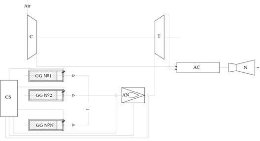
Figure 1. RTEschematic diagram
CS is a control system; GG is a gas generator; AN is an adjustable nozzle; C is a compressor; T is a turbine; AC is an afterburner chamber; N is a nozzle.
Calculation method
The initial data for the calculation (conventional chemical formula and enthalpy of fuel formation) were taken from [2]. The pressure in the combustion chamber (CC) is selected 3; 6; 12 MPa. The pressure after the turbine varied from 0.2 to 0.5 MPa. Thermodynamic calculations were carried out in the Astra 4 software package. The ratio of air consumption to fuel consumption L was calculated using the following formula:
| (1)
|
where  is the difference between the gas enthalpies in the combustor and after the turbine;
  is the enthalpy of the air supplied to the AC;
  and
and  are the air and fuel consumptions from the GG, respectively;
  is compressor efficiency;
  is turbine efficiency. The
  value is found from a thermodynamic calculation, and the value is determined as:

where  and
and  are air enthalpies before and after the compressor, respectively. The value is determined by reference [3]. The results of calculations using formula (1) are shown in Figure 2.
Figure 2. The dependence of L on the pressure after the turbine