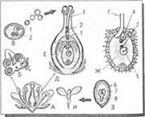
Drugs discovered or made in all across the world by some of our best compassionate scientists teams in remarkably, modern lab conditions. With the help of technology only we are able to develop effective and selective methods for extractions and isolations of those bioactive medicines. For eg:-
| S.NO
| DRUGS
| ACTIONS
| PLANT/ANIMAL SOURCE
|
| 1.
| Acetylgoxin
| cardiotonic
| Digitalis lanaia
|
| 2.
| Aescin
| Anti-inflammatory
| Aesculus hippocastanum
|
| 3.
| Hirudin
| Prevents blood clots
| Leeches
|
| 4.
| Tirofiban / Integrilin
| Blood Thinner
| Viper (Snake)
|
Also, the advancements made in biological science have armed us to effectively deal with many infectious diseases, the use of vaccines & immunization programmed have enabled us to completely eradicate a deadly disease like smallpox. A large no of other infectious diseases like polio, diphtheria, pneumonia and tetanus have been controlled to a large extent by the use of vaccines.
Recognizing diseases and wounds with aid of technology
Very recently, Google acquired Deep Mind a London based start-up focused on deep learning and artificial intelligence processes. Google introduced a machine learning program to detect breast cancer. Google also merged with Calico in 2015 to become a subsidiary of Alphabet Inc. They have developed an experimental a drug compound, P7C3, which could be potentially used in the treatment of Alzheimer’s and other neurodegenerative diseases. On the other hand digital stethoscopes, thermometers etc. have offered more features and improved the accuracy of diagnosis. We all know that health IT tools has support diagnostic team members and improved their practice like El Kareh et al.2013, IOM,2012 aP.78, Computer tomography (CT scans), x-rays etc. There all reduce the potential for diagnostic errors.
Ongoing research on diseases which still cannot be cured fully
Researchers and doctors have been testing different treatments for rare genetic disorder named Wilson disease that currently has no treatment on the market. The disease prevents the body from removing copper that eventually builds up in the organs and can cause life-threatening organ damage and failure sometimes. Others diseases like HIV/AIDS, Alzheimer, Amyotrophic lateral sclerosis (ALS), Adrenocortical carcinoma, also newly found COVID-19(still cure to be found).
We all know that technology provides physiological, biochemical entities that are applied to define diseases. Finally the ultimate goal is that to fight against diseases and eradicate them if possible like polio, Guinea worm disease have eradicated from most parts of the world.
At the dawn knowing that robots and technology can’t replace human doctors as robots don’t have empathy, non-linear working method, also complex technology requires competent professional i.e. humans to operate them. We can say that “Computers are magnificent tools for realisation of our dreams but no machine can replace human spark of spirit, compassion, love and understanding”. But also remember “The only thing that stays the same is change.”
Reference list
1. Guide to understanding Health Technology Assessmant (HTA). – Text : electronic // ICER : Institute for Clinical and Economic Review : [site]. – Boston, 2006 – . – URL: https://icer-review.org/wp-content/uploads/2018/08/ICER-Guide-to-Understanding-Health-Technology-Assessment-6.19.18.pdf (date accessed: 01.03.2020).
2. Federal Food, Drug and Cosmetic Act. – Text : electronic // WIPO – World Intellectual Property Organization : [site]. – URL: https://www.wipo.int/edocs/lexdocs/laws/en/us/us200en.pdf (date accessed: 07.04.2020).
3. Title 10 Department of Health. – Text : electronic // New York Codes, Rules and Regulations : [site]. – URL: https://govt.westlaw.com/nycrr/Browse/Home/NewYork/NewYorkCodesRulesandRegulations?guid=I51d21d50ac3d11dd9f72c1eb90efe723&originationContext=documenttoc&transitionType=Default&contextData=(sc.Default) (date accessed: 15.03.2020).
| Elizaveta Vindokurova
| Елизавета Виндокурова
|
| Perm National Research Polytechnic University
| Пермский Национальный Исследовательский Политехнический Университет
|
| Analysis of changes in deformations of fiber-optic sensors mounted on the surface of structures
| Анализ изменений в деформациях волоконно-оптических датчиков, установленных на поверхности конструкций
|
| Abstract: This article discusses the creation of an algorithm for estimating the distributions of the deformation field after placing a fiber-optic sensor on it. A mathematical model is constructed and calculated. The dependences of the occurrence of the deformation field redistribution on the mechanical properties of the materials are obtained
| Аннотация: В этой статье обсуждается создание алгоритма оценки распределения деформационного поля после размещения на нем волоконно-оптического датчика. Строится и вычисляется математическая модель. Получены зависимости возникновения перераспределения деформационного поля от механических свойств материалов
|
Introduction
Modern fiber-optic sensors (FOS) allow measuring many physical parameters, for example: pressure, temperature, distance, position in space, rotation speed, linear velocity, acceleration, liquid level, deformation, refractive index, electric field, electric current, magnetic field, gas concentration, radiation dose, etc.
The demand for sensors is growing rapidly due to the rapid development of automated monitoring and control systems, the introduction of new technological processes, and the transition to flexible automated production. In addition to high metrological characteristics, the sensors must have high reliability, durability, stability, small dimensions, weight and power consumption, and compatibility with microelectronic information processing devices. FOS meets these requirements to the maximum extent.
The greatest need for fiber optic systems is experienced by rocket and space, aviation and military equipment. FOS can be widely used at enterprises of metallurgical, chemical, oil and gas industries, fuel and energy complex, shipbuilding, mining, automobile transport, medicine, etc.
In order to develop a highly efficient and reliable strain gauge, a mathematical description of the deformation interaction processes of all gauge elements is required. Such mathematical modeling will make it possible to rationally select the basic structural diagram of the sensor.
Accuracy is a very important characteristic of any sensor. True, when they talk about the accuracy of the sensor, most often they mean its inaccuracy or measurement error. Measurement error is usually understood as the value of the maximum discrepancy between the readings of the real and ideal sensors. The measured value is considered to correspond to the real one with a certain degree of confidence.
The sensor error can also be represented as the difference between the value calculated from the sensor output and the actual value of the applied input signal.
Purpose of the work: Creation of an algorithm for assessing the redistribution of the deformation field, as well as determination of the error in the FBG readings as a result of mounting the sensor on the object of study.
Information about optical fiber sensors based on a braggian grille
A fiber Bragg grating sensor is irradiated with light from a broad-spectrum source and the reflected wavelength is measured and matched to the measured parameters. The basic principle of such fiber optic sensors is that the Bragg wavelength (i.e., the wavelength of maximum reflection) in the grating depends not only on the period of the Bragg grating, but also on temperature and mechanical stress.
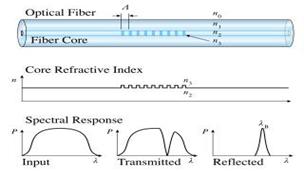
Figure 1-The principle of operation
Redistribution of the stress-strain state of an object after mounting the sensor and determination of the measurement error
The accuracy of the sensor reading is a fundamental quantity that needs to be checked and monitored. When working on real objects, it is necessary to understand exactly what values of the resulting deformation we received. If the object of study is in a uniaxial state, then there are no questions about the accuracy of the measured deformation using the sensor. In practice, however, this is unlikely. When working with real structures, we cannot be completely sure that there are no factors that add additional impact. Therefore, it is very important to understand what exactly we are measuring and what values we get.
There are methods developed to verify the sensor parameters in the field after installation. They were designed to verify the calibration and response times of sensors already in use in a process. However, the use of such methods is not always possible.
All sensors based on the Bragg grating can be combined according to the following criteria:
• The presence of a contact surface sensor-object (housing, substrate)
• The presence of an adhesive bond for fixing the fiber with FBG
• Mounting method (spot welding, adhesive bonding)
In this paper, we consider the place of contact between the sensor and the object by means of adhesive bonding.
The main question that needs to be answered within the framework of the research is whether the redistribution of the stressed state of an object of a machine-building structure occurs after the sensor is mounted on its surface.
To achieve this goal, it is required to solve the following tasks:
• Carry out the formulation of the problem of interaction between the contact area of the sensor and the object of study;
• Develop a finite element model for the analysis of the deformation field;
• Analyze the data obtained and propose an algorithm for selecting the properties of the sensor body to obtain lower stresses in the structure after installation;
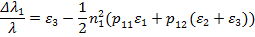
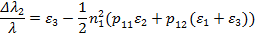
The purpose of this work is to get an idea of the factors affecting the sensor error at the time of installation and to obtain options for minimizing this phenomenon. The relationship between the change in the wavelength of the reflected spectrum and the deformation of the fiber at a constant temperature is determined by the following relations
| (1.1)
|
Where  is the deformation along the fiber,
  are the main deformations in the plane perpendicular to the optical fiber. Δλ1 = λ1-λ, Δλ2 = λ2-λ is the difference in the values of the resonant wavelengths of the reflected spectrum at the current (λ_1, λ_2) and initial (λ) moments of time, n_1 is the refractive index of the optical fiber, p11, p12 are the Pockels coefficients.
Under uniaxial deformation of an optical fiber free from interaction with the environment, deformation
| (1.2)
|
However  . For used optical fibers k = 0.78.
Modeling
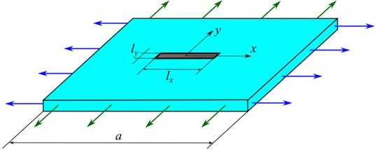
Figure 2- Mathematical model of a plate with a sensor
Mathematical model was created that describes the interaction of the materials of the sensor and the sample.
Dimensions:
 ,
,  ,
,  ,
, 
Where  is the length of the contact area of the sensor (substrate),
  is the width of the contact surface of the sensor (substrate), a is the overall dimensions of the sample,
  is the thickness of the sample,
  is the thickness of the substrate.
The main indicators by which the results of mathematical modeling are compared are the parameters of materials:
• E-modulus of elasticity
• ν-Pausson coefficient
Since there are many options for materials used for the manufacture of sensor cases, it was decided to analyze the interaction of materials whose physical and mechanical parameters differ by an order of magnitude. Examples of selected relationships:
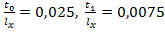
 =1, =1,  =1, ν=0.3, =1, ν=0.3,
 =10, =1, ν=0.3, =10, =1, ν=0.3,
 =100, =1, ν=0.3, и т.д. =100, =1, ν=0.3, и т.д.
|
where is the elastic modulus of the substrate material,  -is the elastic modulus of the material of the test sam0ple -is the elastic modulus of the material of the test sam0ple
|
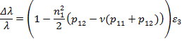
In the center of the sample, a point was fixed where the sensor will be mounted later. A tensile load is applied on two opposite sides of the specimen. The values of deformation ε_ (x) and ε_ (y) of the sample free from the sensor were obtained. The next step was the installation of the sensor, simulating an adhesive bond with full adhesion to the sample. This connection was set using a bonded contact (connected movement of two objects). A variant of the finite element mesh is shown in Figure 3. After the calculation at the initially selected point on the sample, the values ε_ (x1) and ε_ (y1) were obtained.
Formula 1.3 was used to calculate the error arising after mounting the sensor on the surface of the object under study. Several calculations with different mesh discretization were carried out to select the optimal number of finite elements
(with the same GU). Figure 4 shows the change in the strain field after placement on the surface of the sensor substrate.
 , Where
  is the relative error in measuring the deformation, u_z is the projection of the movement of the point under study on the z axis,
  is the distance from the point to the axis of symmetry,
  is the ideal deformation value. In this case, the "-" sign will mean that the measured deformation turned out to be greater than the specified value ..
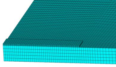
Figure 3 - A variant of a finite element mesh near the substrate (a quarter of the mesh is shown)
| а
| 
| б
| 
|
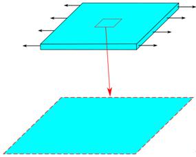
Figure 4 - Pattern of deformation distributions on the surface: a) without a sensor, b) with a sensor
Results
The first stage of the work was to reveal the influence of the material parameter on the redistribution of the deformation field of the research object. As can be noted, according to the results obtained, when the value of Poisson's ratio changes at a fixed value of the elastic modulus, the graphs plotted in Figure 5 do not have noticeable differences. Therefore, it can be concluded that the influence of the Poisson's ratio of the material of the measured object on the redistribution of deformations is weak.
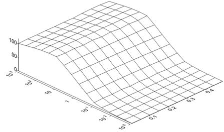
Figure 5- Influence of Poisson's ratio on the redistribution of the deformation field.
At the next stage, it was decided to fix the values of Poisson's ratio v_m = 0.3, since the influence of this parameter on the research object is weak. During the calculations, two parameters were changed: the ratio of the thicknesses of the investigated object and the sensor substrate and the ratio of the elastic moduli. The results are presented in Figure 6 in the form of graphs and isolines.
It can be noted that the thicker the object of study relative to the thickness of the body, the effect decreases. And the more the body material is gesture, the more influence it has. These graphs can work as an algorithm for selecting the material of the sensor body for various designs.
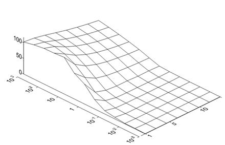
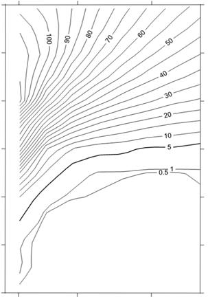
Figure 6- Influence of the ratio of the elastic moduli and the ratio of the thicknesses of the investigated object and the sensor substrate on the redistribution of the deformation field.
Conclusions
A model has been developed for the numerical analysis of deformation changes when placing fiber-optic sensors on substrates on the surface of structures.
An insignificant influence of the Poisson's ratio of the material of the measured object on the redistribution of deformations was revealed.
The results are obtained that allow us to evaluate the change in deformations.
in a structure when placing fiber-optic sensors on its surface, depending on the ratio of mechanical characteristics and geometric dimensions of the structure and the contact surface of the sensor.
The results obtained make it possible to evaluate the main characteristics of the structure, at which the use of the selected sensor on a substrate
Does not introduce significant distortions into measured deformations. We do not say that FBG-based sensors are not accurate, we conditionally introduce additional corrections to process the results and obtain real deformations depending on the characteristics of the material. This algorithm is suitable not only for fiber optic sensors, but also for other sensors.
Reference list
1. Matveenko, V. P. Theoretical substantiation of the possibility of constructing a fiber-optic system for monitoring deformations of the earth's surface / V. P. Matveenko, V. A. Fedorova, I. N. Shardakov // Izvestiya rossiyskoy akademii nauk. Solid mechanics. 2013. №. 5. P. 46–52.
2. Field testing of building structures - step to incresing deformation security / G. N. Gusev, V. P. Matveenko, R. V. Tsvetkov [et al.] // Bulletin of Perm Scientific Center, Ural branch, Russian Academy of Sciences. 2014. №. 4. P. 4–11.
3. Analytical and numerical solutions within the framework of the kosser continuum as a basis for setting up experiments on the detection of moment effects in materials / V. V. Korepanov, M. A. Kulesh, V. P Matveenko, I. N. Shardakov // Computational mechanics of continuous media. 2009. V. 2, № 4. P. 76–91.
| Elena Gachegova
| Елена Гачегова
|
| Perm National Research Polytechnic University
| Пермский Национальный Исследовательский Политехнический Университет
|
| Application of laser shock peening toimprove the fatigue properties of titanium alloy
| Применение лазерного шока для снятия усталости титановых сплавов
|
| Abstract: The article investigates the possibilities of laser shock peening in the field of improving the fatigue properties of the titanium alloy OT4-0. Within the framework of the chosen topic, a literature review was carried out to confirm the relevance of the research direction, as well as to search for a basis for experiments. Then the experiment was set up on laser processing of titanium alloy specimens with predetermined optimal parameters, and fatigue tests were carried out for the peened and unpeened specimens.
| Аннотация: в статье исследуются возможности лазерного шокового ограждения в области улучшения усталостных свойств титанового сплава OT4-0. В рамках выбранной темы был проведен обзор литературы для подтверждения актуальности направления исследований, а также для поиска основы для экспериментов. Затем был запущен эксперимент по лазерной обработке образцов титановых сплавов с заранее установленными оптимальными параметрами, и были проведены испытания на усталость очищенных и непроконсервированных образцов.
|
Introduction
Fatigue failure is one of the main causes of failure of parts and structures that are exposed to stresses cyclically changing in time. Prolonged cyclic load change leads to failure at stress amplitudes below yield strength [1-2]. Particularly relevant issues of forecasting and increase of fatigue life are in the field of aircraft construction, as failure of aircraft structures, as a rule, leads to disasters with serious consequences.
At present, laser shock peening (LSP) is one of the most promising methods to increase fatigue life of metal structural elements [3]. The essence of this method is that short-term high-energy pulses are used to create a plasma on the surface of the material, which expands very quickly. Water acts as a plasma limiter, causing shock waves to be generated on the surface and propagate deeper into the material. These waves plastically deform the material, as a result of which residual stresses appear in the specimen, which contribute to the strengthening of the material.
In recent years, many studies have been conducted on the impact of laser shock peening on fatigue characteristics of specimens. In paper [4], the impact of laser shock peening on fatigue behavior of Fe-Cr alloy specimens with one side cut is considered. Achinta et al. [5] estimated the influence of the size of the area treated with LSP on fatigue properties of AA2024-T3 specimens. The results showed that specimens with a less treated surface around the hole can withstand more loading cycles than specimens hardened across the entire width. The paper [6] considered the influence on fatigue life of such factor as the direction of LSP with respect to the direction of the rolled products. In the experiment, specimens from stainless steel Duplex 2205 were used. The stage of laser processing was divided into two stages: the first arm of the manipulator moved along the direction of rolled products, the second - across. As a result, it was found that when the LSP is perpendicular to the rolled products, the increase in fatigue life reaches 79%, while in the parallel direction it reaches only 35%. Fomin et al. [7] studied the effect of LSP on fatigue properties of Ti-6Al-4V butt joints welded with laser beam. It was noted that LSP mainly affects surface defects rather than internal ones. As for fatigue life, it increased three times after processing.
Based on the considered works, it can be concluded that for the successful use of laser shock peening, it is necessary to carefully select the process parameters for each material and geometry of the parts individually. Thus, the goals of this work were to find the optimal parameters of LSP for the OT4-0 titanium alloy and to analyze the effect of this process on the fatigue characteristics of the material.
1. Materials and methods of surface treatment
Investigated specimens
Titanium alloy OT4-0 was chosen as the material under study. It is used for the manufacture of complex shaped parts operating at medium to high temperatures. It is widely demanded in various branches of modern mechanical engineering. The geometry of the specimens is shown in Figure 1.
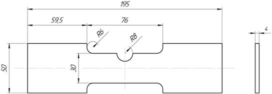
Figure 1. Geometry of specimens