Lesson 1. Pumps
| suction piping
| всасывающий трубопровод
|
| discharge piping
| нагнетательный трубопровод
|
| suction head
| высота всасывания
|
| discharge head
| высота нагнетания
|
| displacement pump
| насос объемного типа
|
| axial flow pump
| осевой насос
|
| centrifugal pump
| центробежный насос
|
| reciprocating pump
| поршневой насос
|
| rotary pump
| роторный насос
|
| air vessel
| воздушный демпфер
|
| relief valve
| предохранительный клапан
|
| adjusting screw
| регулировочный винт
|
| bonnet assy
| колпак
|
| rotary vane displacement pump
| роторный лопастный объемный насос
|
| gear displacement pump
| шестеренный (зубчатый) объемный насос
|
| screw displacement pump
| винтовой объемный насос
|
| casing
| корпус
|
| gland
| уплотнение
|
| driving shaft
| ведущий вал
|
| guide vane
| направляющая лопатка
|
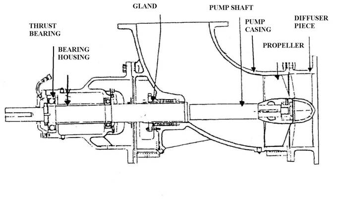
| thrust bearing
| упорный подшипник
|
| bearing housing
| корпус подшипника
|
| diffuser piece
| диффузорная часть
|
| impeller
| крылатка
|
| volute
| улитка
|
| single-entry centrifugal pump
| односекционный центробежный насос
|
| liquid path
| отверстие для выхода жидкости
|
| discharge nozzle
| нагнетательный патрубок
|
| impeller rotation
| зд. направление вращения крылатки
|
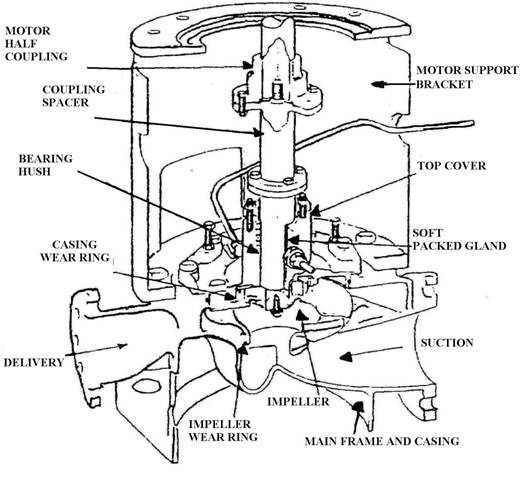
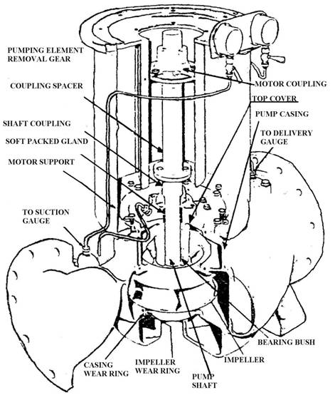
| motor half coupling
| приводная полумуфта
|
| spacer
| шайба, распорка, прокладка
|
| bearing bush
| втулка подшипника
|
| motor support bracket
| приводная полумуфта
|
| soft packed gland
| мягкая набивка
|
| shaft coupling
| соединительная муфта валопровода
|
| globe valve
| тарельчатый клапан
|
| non-return valve
| невозвратный клапан
|
| check valve
| пробный клапан
|
| gate valve
| клинкетный клапан
|
| wedge face
| поверхность клина
|
| wedge gate
| посадочное место клина
|
A pump is a machine, used to raise liquids from a low point to a high point. A pumping system on a ship consists of suction piping, a pump and discharge piping. Even pump has a power end, which may be a steam turbine or an electric motor and a liquid end where the liquid enters or leaves the pump. The typical characteristics for the pump are the suction head and the discharge head. The suction head is the pressure of the liquid entering the pump or the difference in the level of liquid with respect to the level of the pump on the suction side. The discharge head is the pressure of the liquid leaving the pump or the level of liquid with respect to the level of the pump on the discharge side.
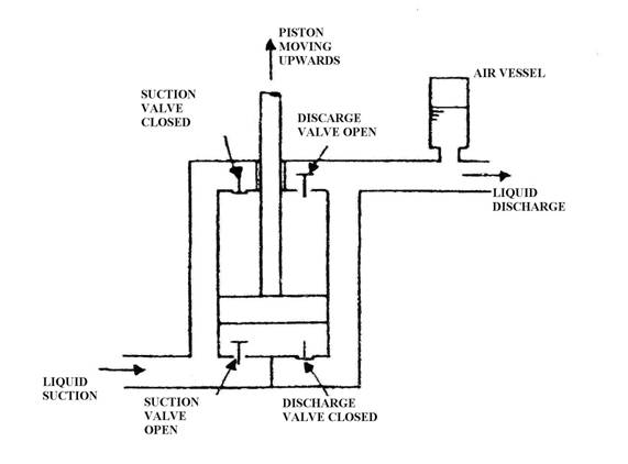
There are three main classes of pumps in marine use: displacement, axial flow and centrifugal. Displacement pumps can be either reciprocating or rotary. The operating principle of the reciprocating displacement pump is the following. As the piston moves upwards suction takes place below the piston and liquid is drawn in, while the discharge valve is closed. Above the piston liquid is discharged and the suction valve is closed. As the piston travels down the operations of suction and discharge occur on opposite sides.
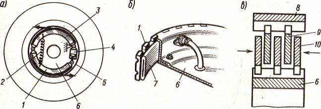
A relief valve is always fitted between the pump suction and discharge chambers to protect the pump against excessive pressure.
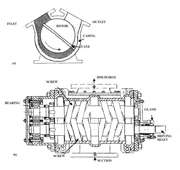
The rotary displacement pumps operate by means of rotary parts which trap the liquid at the suction side and force it through the discharge outlet. According to the type of rotary elements there are rotary vane displacement pumps, gear displacement pumps and screw displacement pumps.
An axial flow pump uses a screw propeller to axially accelerate the liquid. The outlet passages and guide vanes are arranged to convert the velocity increase of the liquid into a pressure.
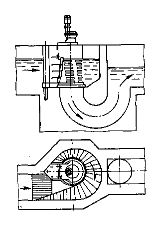
In a centrifugal pump liquid enters the centre of the impeller and flows radially out between the vanes. A diffuser or volute is then used to convert most of the kinetic energy in the liquid into pressure. There are single entry or double entry centrifugal pumps.
Various valves are fitted to the pumps. These include the following: globe valves, non-return or check valves; relief valves.
Exercise 1. Answer the following questions.
1) What is a pump?
2) What does a pumping system on a ship consist?
3) What are the typical characteristics for the pump?
4) What is the suction head?
5) What is the discharge head?
6) How many main classes of pumps are used in marine use? What are they?
7) What is the operating principle of the reciprocating displacement pump?
8) How do the rotary displacement pumps operate?
9) What kinds of pumps are defined according to the type of rotary elements?
10) What for does an axial flow pump use a screw propeller?
11) What for are the outlet passages and guide vanes arranged?
12) What are two types of the centrifugal pumps?
Exercise 2. Give Russian equivalents for the following.
1) Difference
2) with respect to
3) by means of
4) to occur
5) according to
6) to have a power end
7) the operating principle
8) to flow radially
Exercise 3. Translate into English.
1) Насос объемного типа может быть двух видов: поршневой или роторный.
2) В зависимости от типа роторных элементов различают три вида насосов: роторный лопастный объемный насос, шестеренный объемный насос и винтовой объемный насос.
3) В центробежных насосах жидкость движется по центру крылатки и вытекает между лопатками.
4) Насосы оснащены различными клапанами, включая тарельчатый клапан, невозвратный клапан, пробный клапан и предохранительный клапан.
Comprehensive reading
Exercise 1. Read and translate the text.
Operation and maintenance instructions
Starting (the centrifugal pump and axial flow pump)
1) Open the suction check valve wide, opening at the same time the air vent on the top side.
2) Close the air vent as soon as liquid flows out of it.
3) Start the motor leaving the discharge valve closed.
4) Check that direction of rotation is as indicated by the arrow.
5) Slowly open the discharge check valve until operating requirements are reached.
6) Check on the ammeter that power requirements do not exceed the motor possible rating.
7) Check tightness of the packing gland. Leaks must be reduced to a few drops which is required to prevent harmful heating of the packings and the shaft.
During operation
The pump output is to be controlled by operating on the discharge valve and never on the suction valve which must always remain wide open.
Stopping
After switching off the motor close the suction and the discharge valves of the pump.
Exercise 2. Study words and expressions.
| arrow
| стрелка
|
| direction
| направление
|
| requirement
| требование
|
| ammeter
| амперметр
|
| to exceed
| превышать
|
| rating
| расчетная величина
|
| tightness
| герметичность, зд: затяжка
|
| packing gland
| сальник, уплотнение вала
|
| output
| производительность
|
| to prevent
| предотвращать
|
| Pump Type
| Basic Description
| Key Features
| Applications Used
| Recommended Media (Fluid)
| Advantages
| Flow Rate Ranges
| Total Head Ranges
| Horse Power Ranges
|
| Centrifugal Pumps
| General name for pumps with one or more impellers. Many types and configurations for different applications.
| One or more impellers. Casing is volute or diffuser type. Electric motor driven, or other drive.
| All sorts of liquids can be pumps with them. Liquid should not contain air or vapors and have low viscosity.
| Water and relatively thin liquids (won't pump thicker oils). Can pump liquids with or without solids if proper impeller type is chosen.
| Best pump choice for lower viscosity (thin) liquids. Highest flow rates of all pump types.
| 5 -200,000 gpm
| 10 - 7,500 ft
| 0.125 –
5,000 hp
|
| Axial Flow Pump
| Axial Flow pumps are a very high flow, low head type of pump. Also called a propeller pump.
| Single stage, high specific speed impeller for high flow low head.
| Flood dewatering, power plant circulating water pump, evaporator services, and irrigation.
| Water and relatively thin liquids. Can pump liquids with or without solids if proper impeller type is chosen.
| This pump type is the best type to achieve very high flow rate with very low head.
| 5,000 200,000 gpm
| 10 30 ft
| 10 - 1,500 hp
|
| Piston Pump
| Piston pumps are a type of reciprocating positive displacement pump that has, double acting reciprocating pistons.
| Pump includes one or more double acting pistons, an inlet and outlet check valve for each piston.
| In applications where high pressure is needed.
| Water and other thin liquids, including liquids containing abrasives.
| Slower speeds may mean less maintenance.
| 5 - 700 gpm
| 50 - 5,000 psi
| 1 - 500 hp
|
| Pump Type
| Basic Description
| Key Features
| Applications Used
| Recommended Media (Fluid)
| Advantages
| Flow Rate
| Total Head
| Horse Power
|
| Screw Pump
| Screw pumps use two inter-meshing screws, driven by timing gears, move oils and other viscous liquids.
| meshing screws don't drive each other.
| Fuel transfer, elevators, and if needed relatively high flow rates of viscous liquids.
| Oils, fuels, and other high viscosity liquids. Also handles two-phase liquid/gas mixtures.
| Highest flow rate of positive displacement pumps.
| 50 - 15,000 gpm
| 50 4,500 psi
| 5 - 5,000 hp
|
| Gear Pump
| Liquid is pumped by passing between two meshing gears and the surrounding casing. There are internal and external gear types.
| Internal and external gear types. Doesn't handle solids or abrasive liquids.
| Most common pump for clean oils and other viscous liquids.
| Oils and other high viscosity liquids. Usually only suited for clean liquids (no solids).
| Most widely used for clean oil services. Few moving parts, simple construction.
| 1 - 1,500 gpm
| 10 - 2,500 psi
| 0.5 – 2,000 hp
|
| Vane Pump
| Vane pumps use a rotor with vanes located in slots, rotating inside a shaped casing. As the rotor turns, the vanes move in and out of the slots.
| Sliding vanes are often made of carbon.
| An alternative to a gear pump for transferring oils and other viscous liquids. Also good for thinner liquids.
| Oils and other high viscosity liquids. Usually only suited for clean liquids (no solids). Also good for thin liquids like gasoline and water.
| Good for both thick and thin liquids, so often chosen for terminals and truck unloading where many types of liquids are handled.
| 5 - 2,500 gpm
| 20 - 200 psi
| 1 -300 hp
|
Comprehensive reading
What is a Centrifugal Pump?
Centrifugal pumps are usually quick to install, require less maintenance than other alternatives, and the most standard centrifugal pumps are easy to repair. Centrifugal pumps are usually the best choice for lower viscosity (thin) liquids and high flow rates. Multi-stage centrifugal pumps have more than one impeller, and are used for applications that require higher pressure or head.
Piping connections on centrifugal pumps are available with standard pipe threads on smaller sizes, and flanges on larger sizes. The normal drivers supplied with centrifugal pumps are A.C. induction motors, but some pump manufacturers offer pumps with D.C. drives or adaptable to other power transmission devices such as engines and gear boxes.
A centrifugal pump works by directing the liquid in the system into the suction port of the centrifugal pump and from there into the inlet of the impeller. The rotating impeller moves the liquid along the spinning vanes, which increases the velocity energy of the liquid. The liquid leaves the impeller vanes and then moves into the pump volute or diffuser casing, where the high velocity of the fluid is converted into high pressure through a diffusion process. The fluid is then guided into the discharge port of the centrifugal pump and from there out into the system, or on to the next stage in the case of a multi-stage centrifugal pump.
What is an axial flow pump?
An axial flow pump is a type of centrifugal pump that uses an impeller with vanes that direct the flow axially. In this way, they differ from most other centrifugal pumps, which direct the flow more radially. In general, axial flow pumps create less pressure (head) than radial flow centrifugal pumps, but they can produce much higher flow rates.
What is a gear pump?
Gear pumps are considered rotary positive displacement pumps. Gear pump are most common type of positive displacement pump. Like all positive displacement pumps, gear pumps are fixed displacement pumps, meaning that an unchanging volume of liquid moves through at a constant rate provided the pump speed is constant.
How do gear pumps work?
A gear pump uses a rotating set of gears. The moving gears create suction at the inlet port of the pump that draws the fluid into the gears. The rotating gears then move the liquid between the teeth of the gears and the walls of the casing and direct the fluid flow to the discharge port, where the pressure continues to build as the volume of the casing gets smaller near the outlet of the pump. There are two main types of gear pumps. Both consist of a drive gear (the gear that pushes) and an idler (the gear that is pushed).
What is a Piston Pump?
A piston pump is a type of reciprocating pump, which is one of the two major types of positive displacement pump. The piston pump moves and pressurizes fluid using one or more reciprocating pistons, which are normally driven by an electric motor through a crankshaft and connecting rod.
How do Piston Pumps work?
Like most types of positive displacement pumps, piston pumps use the force of the pumping mechanism to expand and contract an internal movable volume of liquid. The power to drive the piston is supplied by an electric motor, internal-combustion engine, or other power source - although more primitive piston pumps may be driven by hand, wind, or flowing water.
The motion behind the piston is usually rotational. Piston pumps can be single acting or double acting. Double acting piston pumps have pumped fluid on both sides of the piston, and two sets of check valves, one on each side of the piston. While the piston is in-taking on one side, it is exhausting on the other. Thus, each time the piston moves in one direction from one end to the other, a full pumping cycle (intake and discharge) has been completed. For single acting piston pumps, the piston must move in both directions to complete a full pumping cycle.
What is a screw pump?
A screw pump is a positive displacement pump that uses two or more intermeshing screws to pressurize fluids in order to pump them in a system. Screw pumps are a type of rotary pump, meaning that they use rotary motion to create a vacuum that draws fluid into the pumping chamber. The meshing screws then push the liquid out the other side with increased pressure.
How do screw pumps work?
There are two major types of screw pumps: two-screw or double screw pumps, and triple screw pumps. Double screw pumps have two intermeshing screws. However, with a double screw pump, one screw cannot drive the other one. So the double screw pump is normally equipped with a set of timing gears, located outside the pumping chamber, and lubricated with clean oil, to ensure that the two screws are rotating correctly relative to each other. With this arrangement, the two screws are not required to be in direct contact with each other. Triple screw pumps have one driving screw intermeshed with two driven screws. This pump type has the screws making contact with each other, so this pump type is limited to cleaner liquids.
What is a vane pump?
A vane pump is a type of positive displacement pump that uses the back and forth movement of rectangle shaped vanes inside slots to move fluids.
How do vane pumps work?
A vane pump includes a cylindrically-shaped rotor turning about its centerline inside of an asymmetrically- shaped casing. The cylindrical rotor has a number of rectangle shaped slots running linearly along the outside of the cylinder. As the cylindrical rotor turns, centrifugal force causes the vanes to move outward, such that the outer edge of the vane stays in touch with the inside surface of the asymmetrically-shaped casing. Like many rotary pumps, the direction of flow can be reversed by reversing the direction of rotation of the pump.
Figures of:
Diagrammatic reciprocating displacement pump
Rotary displacement pumps: (a) rotary vane displacement pump, (b) screw displacement pump.
Axial-flow pump
Centrifugal pump operation
Single-entry centrifugal pump

Double-entry centrifugal pump
UNIT ONE. AUXILIARIES
WORDS AND EXPRESSIONS
| auxiliaries
heat exchanger
distillation equipment
bilge water
sewage treatment plant
incinerator
to range
multi-stage
crank
second stage piston assembly
first stage cooler tubes
first stage drain
second stage drain
steady reading
moisture
to clear
reciprocating machinery
troublesome
rapid
to reface
incorrect
dirt
to stick
to pit
to strip
to lap
reassembly
seal
| вспомогательные двигатели
теплообменник
опреснительное оборудование
льяльные воды, сточные воды
установка для обработки сточно-фекальных
вод
инсинератор
колебаться (от)
многоступенчатый
кривошип
поршневой блок второй ступени
охладитель первой ступени
клапан продувания первой ступени
клапан продувания второй ступени
устойчивое показание (прибора)
влага
очищать
поршневые механизмы
причиняющий беспокойство
быстрый
зд: восстанавливать поверхность (притиранием)
неправильный зд: нерекомендованный
грязь
зд: заклинивать
подвергаться язвенной коррозии
разбирать
шлифовать
повторная сборка
герметичность
|
TEXT
Machinery other than the main propulsion unit is usually called auxiliary. These include the following: air compressors, heat exch angers, distillation equipment, oil / bilge water separators, sewage treatment plants and incinerators.
AIR COMPRESSOR
Compressed air has many uses on board ship ranging from diesel engine starting to the cleaning of machinery during maintenance. The air pressures of 25 bar or more are usually provided in multi-stage machines. Here the air is compressed in the first stage, cooled and compressed to a higher pressure in the next stage and so on. The most common is two-stage crank machine.

(Figure 4.1 Two-stage compressor, p.)
STARTING
The compressor motor is started. The lube oil pressure should reach the correct value. The first stage drains and then the second stage drains are closed and the machine will begin to operate. The pressure gauge cocks should be adjusted to give a steady reading. Where manual drains are fitted they should be slightly opened to discharge any moisture which may collect in the coolers. The cooling water supply should be checked as well as operating temperatures.
STOPPING
To stop the compressor the first and second-stage cooler drain valves should be opened and the machine run unloaded for 2 or 3 minutes which will clear the coolers of condensate. The compressor can now be stopped and the drains should be left open.
HEAT EXCHANGERS
WORDS AND EXPRESSIONS
| to require
conducting surface
opposite
counter or contra flow
fairly
heat transfer
shell and tube cooler
plate type heat exchanger
tube bundle
corrosion resistor
visible joint
radial flow circular baffles
safety expansion ring
double joint
removable cover
shell
frame plate
carrier bar
support post
tie bolt
plate pack
guide bar
| требовать
проводящая поверхность
противоположный
противопоток
довольно
теплопередача
трубчатый охладитель
пластинчатый охладитель
пучок труб
антикоррозийный протектор
наружное соединение
направляющие пластины потока
предохранительное расширительное кольцо
рамовая плита
балка
корпус, кожух
поддерживающая опора
стяжной болт
зд: двойное уплотнение
съемная крышка
пакет пластин
направляющая балка
|
TEXT
Heat exchangers on board a ship are mainly coolers where a hot liquid is cooled by sea water. There are some instances where liquid heating is required, such as heavy fuel oil heaters and sea water heaters for tank cleaning.
In the heat exchange process the two liquids pass on either side of a conducting surface. The heat from the hot liquid passes to the cold liquid and the conducting surface is at a temperature between the two. Marine heat exchangers usually have the two liquids flowing in o pposite directions, i.e. counter or contra flow which provides a fairly constant temperature difference between the two liquids and therefore the maximum heat transfer.
Coolers at sea fall into 2 groups: the shell and tube and the plate type. Heaters are similar in construction to coolers.
In the shell and tube design a tube bundle is fitted into a shell.

Figure 4.2. Shell and tube cooler,
The plate type heat exchanger is made up of a number of pressed plates surrounded by seals and held together in a frame.

Figure 4.3 Plate-type heat exchanger: (a) construction.
WORDS AND EXPRESSIONS.
troubleshooting - выявление повреждений
to reduce - уменьшать, снижать
considerably - значительно
filling - заполнение
occasionally - изредка, время от времени
afterwards - впоследствии
circumstance - обстоятельство
О- ring - уплотнительное кольцо
connection - связь, соединение
gasket - прокладка
sealing surface - уплотняющая поверхность
deposits - отложения
flow rate - расход
visible - видимый
further - далее, затем, зд: сильнее
deformed - деформированный
double - двойной
adjoining plate - прилегающая (примыкающая) пластина
volume - объем, размер
to decrease - уменьшать
respective - соответствующий
hole - отверстие
to apply - применять
opposite side - противоположная сторона
TEXT
Temperature of coolers is controlled by adjusting the cooling liquid outlet valve. The inlet valve is left open which ensures a constant pressure within the cooler. This is very important with sea water cooling where reducing pressure can result in air remaining in a cooler which will considerably reduce the cooling effect. Vents provided in the highest point of coolers should be opened on first filling and occasionally afterwards. Drain plugs are also fitted at the lowest point in coolers.
The plate heat exchangers should be opened and cleaned regularly and under normal circumstances every six months. The Q-rings in the connections, the gaskets and the sealing surfaces on the back of the plate should be checked before the heat exchanger is reassembled.
WORDS AND EXPRESSIONS
| pure
evaporation
re-condensing
boiling process
flash process
overflow weir
seawater feed
brine discharge
condenser nest
shell drain
demister
heater nest
jacket water inlet
jacket water outlet
alternative steam connections
anti-pollution regulations
stringent
to contain
purity
legislative
requirements
monitoring unit
continuously
alarm unit
warning
oil collection space
filter insert
pilot valve
coarse (fine) separating compartment
catch plate
legislation
to install
waste water inlet
chlorine contact
aeration
settling
coarse screen
sludge
soil
ultimate
in conjunction with
thus
waste disposal package
| чистый
испарение
реконденсация
процесс кипения
процесс мгновенного парообразования
переливной патрубок
вход забортной воды
выход рассола
конденсаторный отсек
слив из корпуса
каплеотбойник
отсек подогревателя
вход греющей воды
выход греющей воды
альтернативные паровые соединения
правила предупреждения загрязнения
жесткий
содержать
чистота,
законодательный
требования
блок мониторинга
постоянно
сигнальное устройство
предупреждение
сборник нефтепродуктов
фильтрующий элемент
управляющий клапан
отсек грубой (тонкой) очистки
захватывающая пластина
закон
устанавливать
вход загрязненной воды
хлорирование
аэрация
отстой
экран грубой очистки
грязь, отстой
зд. активный ил
максимальный
совместно с, в сочетании с
таким образом
блок (набор) уничтожения отходов
|
TEXT
DISTILLATION SYSTEMS
Distillation is the production of pure water from sea water by evaporation and condensing. Distilled water is produced either by a boiling or a flash process.
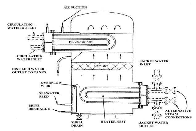
Figure 4.4 Boiling process evaporator.
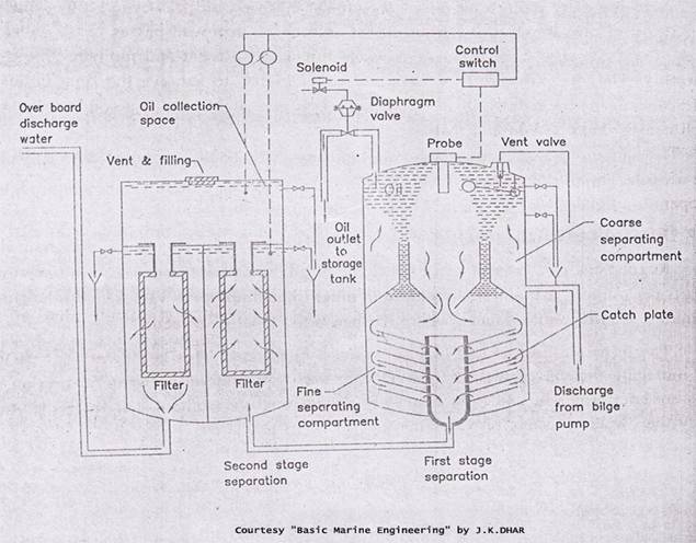
OIL WATER SEPARATORS
Oily water separators are used for separation of oil from water. While anti-pollution regulations are becoming more and more stringent clean water suitable for discharge must contain less than 15 parts per million of oil. As oil/water separators can achieve 100 parts per million a filter must be also used to provide the required purity. The latest legislative requirements are where 100 parts per million purity is required, a monitoring unit which continuously records, and, where 15 parts per million purity is necessary, an alarm unit to provide warning of levels of discharge in excess of 15 parts per million.
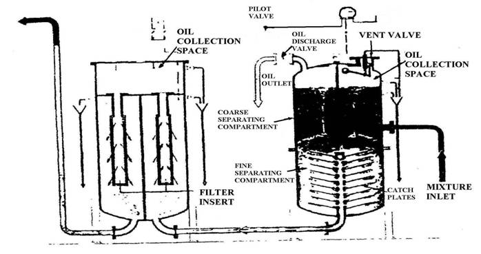
Figure 4.5 Oily water separator.
SEWAGE TREATMENT
To meet certain standards, introduced by International legislation all new ships have sewage treatment plants installed. There are two particular types of sewage treatment plant using either chemical or biological methods.
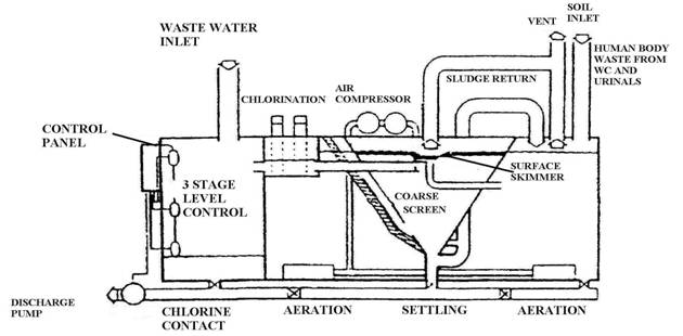
Figure 4.6 Biological sewage treatment plant,
INCINERATOR
To achieve the ultimate situation of no discharge a suitable incinerator is used in conjunction with a sewage plant and with facilities for burning oil sludges thus forming a complete waste disposal package.
WORDS AND EXPRESSIONS
mooring winch - швартовая лебедка
windlass - брашпиль
cargo handling equipment - оборудование для обработки грузов
anchor handling equipment - якорное устройство
hatch cover - люковое закрытие, крышка люка
item - зд: наименование
life-boat - спасательная шлюпка
life-raft - спасательный плот
emergency equipment - аварийное оборудование
watertight door - водонепроницаемая дверь
bow thruster - носовое подруливающее устройство
currently - в настоящее время
winch barrel (drum) - барабан лебедки
warp end - турачка
geared drive - зубчатая передача
self-tensioning unit - уст-во, автоматически поддерживающее заданное усилие
recent development - зд: современный вариант (версия)
split windlass - брашпиль с разделенным приводом
cable lifter - звездочка (брашпиля)
clutch gear handle - ручка привода сцепления
band brake - ленточный тормоз
clutch lever - рычаг сообщения
brake handle - рукоятка тормоза
derrick - грузовая стрела
derrick rig - стреловое устройство
union purchase - спаренные грузовые стрелы, работающие на один гак ("телефон")
quayside - причальная линия
to enable - давать возможность
Samson post - грузовая колонка (полуматка)
stay -оттяжка
topping wire - топенанта
hook - гак
outboard derrick - стрела, вынесенная за борт
to rotate - вращаться
hoisting and luffing motors - механизм подъема груза и изменения вылета стрелы
turntable base - поворотная площадка
operator's cab - кабина крановщика
slewing motor - поворот крана
to expose - подвергаться
enclosure - оболочка, зд: поверхность
splash lubrication - смазывание разбрызгиванием
gearing - зубчатая передача
to grease - смазывать
pressure grease point - пресмасленка
open gear compound - смазка для открытых приводов
to be associated with - быть связанным с, зд: зависеть от
TEXT
Deck machinery includes mooring equipment, anchor handling equipment, саг g о handling equipment and hatch covers. Other items include life-boats and life-rafts, emergency equipment, watertight doors and bow thrusters.
Three forms of power are currently in use for driving deck machinery: steam, hydraulic and electric. Winches with various arrangements of barrels are the usual mooring equipment used on board ships. (Figure 5.1 Mooring winch, p.)
Modern mooring winches are arranged as automatic self-tensioning units.
The windlass is the usual anchor handling device where one machine may be used to handle both anchors.
A more recent development particularly on larger vessels is the split windlass where one machine is used for each anchor. (Figure 5.2. Windlass, p.)
Cargo winches are used with the various derrick systems arranged for cargo handling One of the several possible derrick arrangements or rigs is a derrick rig, known as " union purchase " One derrick is positioned over the quayside and the other almost vertically over the hold. A combination of movements from the two winches enables lifting, transfer and lowering of the cargo. (Figure 5.3. Union purchase rig, p. )
Cranes have replaced derricks on many modern ships. Positioned between the holds often on a platform which can be rotated through 360º the deck crane requires only one man to operate it. (Figure 5.4 General cargo crane, p.)
All deck machinery is exposed to heavy weather. Total enclosure of all working parts is usual with splash lubrication for gearing. The various bearings on the shafts must be greased by pressure grease points. Open gears and clutches are lubricated with open gear compoun d Particular maintenance tasks are associated with the type of motor drive used.

Figure 5.1 Mooring winch.
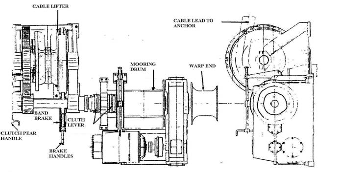
Figure 5.2. Windlass
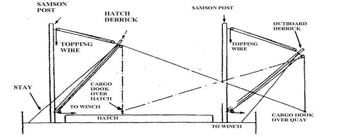
Figure 5.3. Union purchase rig.
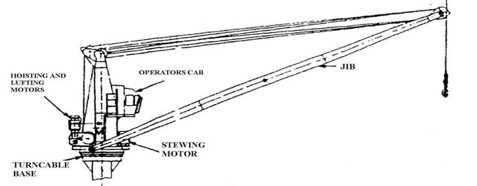
Figure 5.4 General cargo crane
Part Two. Lubricating Oil.
Lubrication is necessary to dissipate heat caused by friction, reduce friction and combat wear and tear between the surfaces of two moving components. The lube oil has the following properties: viscosity, volatility, alkalinity, detergent and oiliness. The viscosity must be calculated by taking into consideration the application and operating temperature range. Volatility should be taken into account to prevent crankcase explosions. Alkalinity is especially important for the cylinder lubrication, as it acts as a neutralizer to the acidic sulphur residues from combustion of HFO. Detergents are added to the lube oil to inhibit (замедлять) the formation of deposits of the moving components, also it helps to keep the oil clean.
To maintain the lubricating oil's operating parameters and properties, the temperature and pressure must be controlled. The solids and water should be removed from the oil through centrifuging. The use of low quality lubricating oil can lead to several problems:
1. Less amount of lube oil in circulation causes rise in temperature thus reducing the viscosity leading the failure of boundary lubrication due to decrease in oil film thickness.
2. Lubrication oil properties can be lost or the oil viscosity will increase.
3. Increase in friction, wear, heat corrosion, contamination and noise and it reduces the engine performance.
The purifying of the oil is also necessary to maintain the original properties of the oil. Knowing the quantity of engine oil, the rule states that the amount of system oil depends on the type of engine. It should be 1lit/bhp and lube oil should not circulate more the 15 times/hr.
In daily operation, the lube oils of diesel engines are continuously contaminated. All rotating or sliding parts deposit metal impurities. Added to this are residues of the combustion process, condensed water decomposition products which settle in the lube oil sump. The oils themselves can also contain acids which, in combination with catalyzing foreign substances, can result in premature ageing of the oil. At the same time, on diesel engines, residues of the combustion process and incombustible constituents from the cylinder can also reach the lube oil circuit. These residues can lead to considerable symptoms of wear at bearing points, pistons and cylinders.
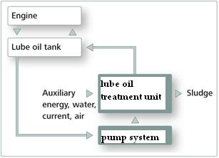 Lube Oil Treatment Lube Oil Treatment
| Answer the following questions:
1. What is the main property of oil? Why?
2. What can the quality of the oil be worsen?
3. What are the problems caused by using the low quality of oil?
4. How is lube oil contaminated?
5. What do you know about lube oil treatment?
|
Exercise I. Put the verbs from the brackets in the correct form.
1. If the viscosity of the oil is too great, it ___ (to affect) the operation of the moving components against each other-offering greater resistance to motion.
2. If the viscosity is too low it ____ (to be able, to flow) too freely between the surfaces of the components, failing to lubricate them properly.
3. If the oil’s flash point ___ (to be) low, it ___ (to ignite) due to the high temperature of a hot spot causing an explosion of crankcase. The flash point of a marine diesel engine lube oil ____ (should, to be) above 200°C.
4. The proper treatment ____ (to achieve) aboard ship by maintaining the optimum temperatures and pressures of both the fuel and lube oil through the use of pumps, heaters, and coolers.
5. Cleanliness as well as the regular maintenance and inspection of the lube and fuel oil cleaning components __ (to be) very important and ___ (to carry out) by means of centrifuges and filters.
6. The supply of good quality low sulfur heavy fuel oil ___ (to be) essential to the marine diesel engine combustion process.
7. Due to its properties HFO __ (to require) to be kept at high temperature for storage and usage, it __(to achieve) by use of low steam coils in the bunkers and storage tanks and a series of heaters between here and the engine fuel pumps and injectors to keep the oil between 104°F in the main bunkers and 250°F at the main engine injectors.
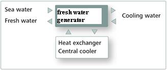
Sea Water Desalination
Storing large quantities of fresh water not only expensive but also takes up a large amount of space. Desalination is based on the evaporation principle: sea water which has been filtered through a coarse mesh is evaporated in a heat exchanger plate stack made of titanium to precipitate salt and impurities. A further plate stack condenses the steam into drinking water. A salt measuring cell now checks residual salt content which is usually below 4 ppm. If a value below this is reliably maintained, the fresh water can be passed into a storage tank and subjected to further treatment in the form of UV sterilization. A re-hardening filter then finally returns enough hardness to the fully demineralized water to make it potable for humans.
| Sea water desalination system
| 
|
| Answer the following questions:
1. What is bilgewater/sludge?
2. How is the bilgewater treated?
3. What is the way of sludge treatment?
4. How can the sludge be disposed?
5. Describe the process of desalination.
|
Vocabulary
Alkalinity is the alkali concentration or alkaline quality of a substance that contains alkali.
The ash content is related to the amount of inorganic material in the fuel.
The carbon residue of a fuel is the tendency to form carbon deposits under high temperature condition in an inert atmosphere, and may be expressed as either Conradson Carbon Residue (CCR) or Micro Carbon Residue (MCR). The maximum limit of carbon residue content in fuel is 22 %.
Detergent is a synthetic cleaning agent or substance.
Density is the relationship between mass and volume at a stated temperature.
The flash point of the liquid is the lowest temperature at which sufficient vapor is given to produce a flash on application of a flame under specified test conditions.
Oiliness is the oil’s ability to adhere to the surfaces such as white metal bearings.
Oil additives are chemical compounds that improve the lubricant performance of base oil. The manufacturer of many different oils can utilize the same base stock for each formulation and can choose different additives for each specific application. Additives comprise up to 5% by weight of some oils.
The pour point is the lowest temperature at which a marine fuel oil can be handled without excessive amounts of wax crystals forming out of solution. At a lower temperature the fuel will gel, thereby preventing flow.
The specific gravity of HFO is its ratio to the density of water at a specified temperature. Bunker oil HFO ranges between 0.95-1.03
Viscosity is a measurement of the resistant of a liquid to shear or flow and is measured in Centistokes (CST) with a quoted reference temperature.
Volatility is the ability of the oil to ignite due to a low flash point.
Vocabulary Section
heavy fuel oil (HFO) – мазут marine diesel oil (MDO) – дизельное топливо
sulfur content – содержание серы
sludge – осадок, шлам
density - плотность specific gravity – удельная плотность
viscosity - вязкость
to be of concern – иметь значение
flash point – температура вспышки
pour point – температура застывания, температура потери текучести нефти
wax formation – парафиновая пленка (воск)
treatment - обработка intermediate - промежуточный
settling tank –отстойная цистерна
day =storage=service tanks –расходные цистерны
to take into account = to take into consideration – принимать во внимание
ash – зола, пепел soot – кокс, сажа, нагар (топливо)
carbon residue – коксовое число (остаток), нагар
contaminant = impurity (impurities) – загрязняющее вещество, примесь
to undergo - совершать, выполнять
to dissipate - рассеивать to combat – противодействовать
friction - трение wear and tear – износ и разрыв
volatility – испаряемость, летучесть
alkalinity – степень насыщения щелочью, щелочность
detergent – моющая присадка (очищающий агент, препятствующий схватыванию)
oiliness – маслянистость, смазочные качества
boundary lubrication – смазка тонким слоем, граничная смазка
film thickness – толщина пленки
constituents - компоненты
to slide - скользить
decomposition - расслоение
oil sump - маслоотстойник
ageing – окисление (топливо, масло)
steam coils – паровые змеевики
Bilgewater – трюмная вода
sedimentation – отложение осадка, процесс отстоя
disposal – утилизация отходов
Recovered – регенерированное (топливо, масло)
Backflush – промывка обратным потоком
precious - точный
site – здесь: место утилизации мусора
coarse mesh – сетка с крупными отверстиями для грубой очистки
plate stack – блок пластин теплообменника
to precipitate – отстаивать, давать осадок
UV sterilization – стерилизация УФ излучением
re - hardening filter – фильтр восстановления минерального состава деминерализованной или дистиллированной воды
additives – присадки для более эффективной работы (топливо и масло)
ONLY FOR ADVANCED
I-1 Pump Safety Tips
Maintenance personnel should be aware of potential hazards to reduce the risk of accidents
Safety Apparel
- Insulated work gloves when handling hot bearings or using bearing heater.
- Heavy work gloves when handling parts with sharp edges, especially impellers
- Safety glasses (with side shields) for eye protection, especially in machine shop areas.
- Steel-toed shoes for foot protection when handling pants, heavy tools, etc.
- Other personal protective equipment to protect against hazardous/toxic fluids.
Couplings Guards:
- Never operate pump without a coupling guard properly installed.
Flanged Connections:
- Never force piping to make a connection with a pump.
- Use only fasteners of the proper size and material.
- Ensure there are no missing fasteners.
- Beware of corroded or loose fasteners.
Operation:
- Do not operate below minimum rated flow, or with suction/discharge valves closed.
- Do not open vent or drain valves, or remove plugs while system is pressurized.
Maintenance Safety:
- Always lockout power.
- Ensure pump is isolated from system and pressure is relieved before disassembling pump, removing plugs, or disconnecting piping.
- Use proper lifting and supporting equipment to prevent serious injury.
- Observe proper decontamination procedures.
- Know and follow company safety regulations.
- Never apply heat to remove impeller.
- Observe all cautions and warnings highlighted in pump instruction manual.
Predictive and Preventative
PUMP PERFORMANCE MONITORING
There are six parameters that should be monitored to understand how a pump is performing. They are Suction pressure (Ps), discharge pressure (Pd), flow (Q), pump speed (Nr), pumpage properties, and power. Power is easiest measured with a clip on amp meter but some facilities have continuous monitoring systems that can be utilized. In any event, the intent is to determine the BHP of the pump. When using a clip on amp meter the degree of accuracy is limited. It should not be used to determine the efficiency of the pump. Clip on amp meters are best used for trouble shooting where the engineer is trying to determine the operating point of the pump.
The most basic method of determining the TDH of the pump is by utilizing suction and discharge gauges to determine PS and Pd. The installation of the taps for the gauges is very important. Ideally, they should be located normal to the pipe wall and on the horizontal centerline of the pipe. They should also be in a straight section of pipe. Avoid locating the taps in elbows or reducers because the readings will not indicate the true static pressure due to the velocity head component. Avoid locating taps in the top or bottom of the pipe because the gauges can become air bound or clogged with solids.
Flow measurements can be difficult to obtain but every effort should be made to do so, especially when trouble shooting. In some new installations permanent flow meters are installed which make the lob easier. When this is the case, make sure the flow meters are working properly and have been calibrated on a regular schedule. When flow meters are not installed, pitot tubes can be used. Pitot tubes provide a very accurate measure of flow, but this in an obtrusive device and provisions must be made to insert the tube into the piping. The other method of determining flow is with either a doppler or transitime device. Again, provisions must be made on the piping for these instruments, but these are non-obtrusive devices and are easier to use than the pitot tube. Caution must be exercised because each device must be calibrated, and independent testing has shown these devices are sensitive to the pumpage and are not 100% accurate.
An accurate power measurement reading can also be difficult to obtain. Clip on tap meters are the most common tool available to the Field Engineer who is trouble shooting a pump problem. In most cases this has proven to be accurate. However, as previously mentioned, this tool must be used and applied properly. Clip on tap meters are not accurate enough to determine the actual efficiency of a pump. If accurate horsepower readings are necessary, a torque shaft must be installed but is not very practical in an actual field installation and lends itself to use in a laboratory environment much better. In some critical installations where the user has provided a permanent power monitor, these have varying degrees of accuracy and they must be understood up front.
Finally, the properties of the pumpage must be known to accurately determine the actual pump performance. Pumpage temperature (TP), viscosity, and specific gravity (S.G.), must be known.
When all of the above parameters are known, it becomes a simple matter of calculating the pump performance. There are instances when it proves to be a very difficult if not an impossible task to determine all of the above parameters in the field, therefore, the Field Engineer must rely on his or her ability to understand where a compromise must be made to get the lob done. The basic document the Field Engineer must have is the pump performance curve. With this it can be determined where the pump is performing in some cases without all of the information.
Lesson 1. Pumps
| suction piping
| всасывающий трубопровод
|
| discharge piping
| нагнетательный трубопровод
|
| suction head
| высота всасывания
|
| discharge head
| высота нагнетания
|
| displacement pump
| насос объемного типа
|
| axial flow pump
| осевой насос
|
| centrifugal pump
| центробежный насос
|
| reciprocating pump
| поршневой насос
|
| rotary pump
| роторный насос
|
| air vessel
| воздушный демпфер
|
| relief valve
| предохранительный клапан
|
| adjusting screw
| регулировочный винт
|
| bonnet assy
| колпак
|