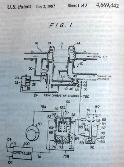
Referring first to Fig. 1 showing the structure of an embodiment of an EGR controlling apparatus according to this invention, a compressor 14 of a turbocharger 12 is provided in an intake air passage 10 of an engine and an exhaust turbine 18 of the turbocharger 12 in an exhaust air passage 16 such that the intake air pressurized by the turbocharger 12 is supplied to a combustion chamber. An actuator 20 is provided for the purpose of suppressing the boost pressure of the intake air to a predetermined value. To a diaphragm chamber 22 of the actuator 20, the intake air on the downstream side of the compressor 14 is introduced through a pipe line 24, and a rod 28 connected to a diaphragm 26 is connected to a waste gate valve 32 provided to close a bypass pipe 30 which functions to bypass the upstream side and the downstream side of the exhaust turbine 18. By these means, when the boost pressure of the downstream side of the compressor 14 exceeds a preset level, the actuator 20 is activated to open the waste gate valve 32. Then the exhaust gas on the upstream side of the exhaust turbinel8 is bypassed to the downstream side, and the driving force of the turbocharger 12 is reduced, thereby preventing the boost pressure from exceeding the preset level.
In order to recirculate exhaust gas, an EGR passage 34 is provided which connects the exhaust air passage 16 at the upstream side of the exhaust turbine 18 and the intake air passage 10 at the downstream side of the compressor 14. In the EGR passage 34 is provided an EGR valve 36 for controlling the amount of EGR, which is composed of a diaphragm 38 for defining a diaphragm chamber 44 into which vacuum is introduced, a rod 40 one of which is secured to the diaphragm 38 and which has a valve body 42 at the other end, and a spring 46 for constantly urging the valve body 42 in the lefthand direction, as viewed in FIG. 1. The valve body 42 of the EGR valve 36 ordinarily closes, by the urging force of the spring 46, the EGR passage 34 which connects the intake air passage 10 and the exhaust air passage 16. Referential numeral 50 denote a vacuum source for supplying vacuum to the diaphragm chamber 44 of the EGR valve 36, and mis vacuum source 50 is connected by a passage 75 to the diaphragm chamber 44 of the EGR valve 36 through a vacuum adjustment valve 60 and a valve device 80.
To describe the apparatus in more detail, the vacuum adjustment valve 60 is substantially composed of a housing 63, a diaphragm chamber 68 into which vacuum is introduced, an atmospheric air chamber 71 which is communicated to atmospheric air, both chambers 68 and 71 being formed in the housing 63 by the division of it into two parts, and a movable valve 65 for controlling the communication of both chambers 68 and 71. In the diaphragm chamber 68 are provided a vacuum introducing passage 61 which is communicated to the vacuum source 50 through a passage 75A and an outlet 62 which is communicated to the vacuum control valve 80 through a passage 75B. The movable valve 65 has a communicating hole 65A, for communicating both chambers 68 and 71, and a valve body 67 for opening and closing the communicating hole 65A, and it is supported as a whole in the housing 63 by the diaphragm 64 which forms a partition between the chamber 68 and the chamber 71. The movable valve 65 is urged by a spring 69 on the upper wall in the direction in which the communicating hole 65A is closed in combination with the valve body 67, and the valve body 67 is urged by a spring 66 in the movable valve 65 in a direction in which the communicating hole 65A is closed. An excitation coil 70 for opening the valve body 67 against the resistance of the spring 66 is provided in the atmospheric chamber 71 and it is electrically connected to a controller 100 which is provided separately from the vacuum adjustment valve 60. The controller 100 fetches a signal showing the running state of the engine, such as an engine rotational speed signal 102, engine load signal 103 and engine coolant temperature signal 104, and on the basis of these signals outputs a driving current In to the exciting coil 70 of the vacuum control valve 60. In correspondence with the driving current In the vacuum adjustment valve 60 controls the vacuum which is to be introduced into the EGR valve 36, whereby the amount of EGR which corresponds with the running state of the engine is obtained.
Referential numeral 72 represents a filter, through which air is introduced to the atmospheric chamber 71.
FIG.2 schematically shows the relationship between the driving current Ip the output vacuum Vp of the vacuum adjustment valve 60. As is obvious from this Figure, the driving current li which accords with the EGR control range is supplied from the controller 100 to the vacuum adjustment valve 60, whereby the vacuum adjustment valve 60 outputs the vacuum Vpl for EGR control. The output vacuum Vp increases with increase of the driving current Ip and the range defined by the driving current II to 12 and the output vacuum Vpl to Vp2 is determined to be the EGR control range.
The vacuum which is indicated by symbol Vpr is the residual pressure which is output even when the running state of the engine is out of the EGR control range and the driving current is 0 ampere.
A vacuum control valve 80 has a vacuum receiving chamber 81 which is connected to the outlet 62 of the vacuum adjustment valve 60 through the passage 75B, and a vacuum control chamber 82 which is connected to the diaphragm chamber 44 of the EGR valve 36 through a passage 75C. The vacuum receiving chamber 81 and the vacuum control chamber 82 are compartmented respectively by the first and second diaphragm 83 and 84, and between the two diaphragms 83 and 84 is formed an atmospheric air chamber 85. The vacuum receiving chamber 81 is able to communicate to the vacuum control chamber 82 through a pipeline 86, which is secured to the first diaphragm 83, penetrates through the atmospheric air chamber 85 and the second diaphragm and extends to the vacuum control chamber 82. In the state shown in FIG. 1, however, an opening 88 at the lower end of the pipe line 86 is closed in contact with a valve body 87 and vacuum is not introduced into the vacuum control chamber 82.The valve body 87 is disposed in a second atmospheric air chamber 89 which is communicated to the vacuum control chamber 82 through the opening 88 and is urged by a spring 90 in such a direction as to close the opening 88.The first diaphragm 83 is urged by a spring 91 downwardly as viewed in FIG. 1, and, hence, the pipeline 86 which is secured to the first diaphragm 83 is also urged downwardly as seen in FIG. 1 against the resistance of valve body 87. The second atmospheric chamber 89 is communicated to atmospheric air through a filter 92. In the state shown in the Figure, atmospheric air is introduced to the vacuum control chamber 82, and the atmospheric air is introduced to the EGR valve 36. When vacuum against the resistance of spring 91 is introduced into the vacuum receiving chamber 81 from the vacuum adjustment valve 60, the first diaphragm 83 and, hence, the pipeline 86 are elevated, and the valve body 87 closes the opening 88 by means of the urging force of the spring 90, whereby the vacuum receiving chamber 81 and the vacuum from the vacuum adjustment valve 60 is directly introduced to the EGR valve 36.
FIG. 3 shows the performance characteristics of the vacuum control valve 80. The input vacuum Vpl and the output vacuum V pO take the same value, but when the input vacuum is under V pO no vacuum is output or, to be more exact, atmospheric air is output. The effective lower limitation value VpO is set to be lower than the lower limitation value Vpl of the vacuum controlling characteristics of the vacuum adjustment value 60 in the EGR control region shown in FIG> 2. This is for the purpose of providing a hysteresis for safely executing the EGR control in the EGR control region.
FIG.4 shows the vacuum controlling characteristics of the embodiment...
Referring to FIG.S which shows another embodiment of this invention* the vacuum control valve in the first embodiment is replaced by a vacuum switching valve.
While there have been described what are at present considered to be the preferred embodiments of the invention, it will be understood that various modifications may be made therein, and it is intended that the appended
claims cover all such modifications as fall within the true spirit and scope of the invention.
What is claimed is:
1. All exhaust gas recirculation apparatus for an internal combustion engine having an intake air passage and an exhaust gas passage connected thereto, said apparatus comprising:
an exhaust gas recirculation passage connecting the exhaust gas passage to the intake passage for recirculating the exhaust gas into the intake air passage;
a vacuum-operated exhaust gas recirculation control valve disposed in said exhaust gas recirculation passage for controlling the flow of the exhaust gas to be recirculated, said exhaust gas recirculator control valve comprising a diaphragm for receiving admitted operating vacuum such that the valve closes when the absolute value of the admitted operating vacuum is lower than the absolute value of a first predetermined vacuum value and opens when the absolute value of the admitted operating vacuum is higher than the absolute value of said first predetermined vacuum value;
a vacuum source and a vacuum line connecting said vacuum source to said exhaust gas recirculation control valve to admit the operating vacuum therefore; a passage regulating valve disposed in said vacuum line between said vacuum source and said exhaust gas recirculation control valve for regulating a source vacuum to create the operating vacuum for said exhaust gas recirculation control valve depending on the driving condition of the engine such that the absolute value of said operating vacuum is higher than the absolute value of said first predetermined vacuum value when the driving condition of the engine is in a predetermined range so as to operate said exhaust gas recirculation control valve; and a low pressure cut-off valve disposed in said vacuum line between said pressure regulating valve and said exhaust gas recirculation control valve and comprising a housing, first and second diaphragms for dividing the housing into first, second and third chambers, a pipe secured to the first diaphragm and extending through the second diaphragm into the third chamber so as to allow fluid communication between the first and third chambers, an inlet opening adapted to communicate the first chamber with the pressure regulating valve, an outlet opening adapted to communicate the third chamber with the exhaust gas recirculation control valve, an air opening adapted to communicate the second chamber with the atmosphere, a further air opening adapted to communicate the third chamber with the atmosphere, a valve seat arranged in said further opening, and a valve clement selectively engaging one or said pipe and said valve seat for transmitting the operating vacuum from said pressure regulating valve to said exhaust gas recirculation control valve when the absolute value of the vacuum in the firm chamber is Inkier than the absolute value of a second predetermined vacuum value, which I lower than the absolute value of said first predetermined vacuum value, and for cutting off the opening vacuum from said pressure regulating valve to said exhaust gas recirculation control valve when the absolute value of the vacuum in the first chamber is lower than the absolute value of said second predetermined vacuum value, whereby said exhaust gas recirculation control valve is prevented from being accidentally opened by a residual vacuum which prevails in said pressure regulating valve when the driving condition of the engine is out of said predetermined range.
2. An exhaust gas recirculation apparatus as set forth in claim I, wherein said low pressure cut-off valve cuts off said opening vacuum and transmits an atmospheric pressure to said exhaust gas inoculation control valve when the absolute value of the vacuum in the first chamber is lower than the absolute value of said second predetermined vacuum value*
3. An exhaust gas recirculation apparatus as set forth m claim 1, further com- prising:
A bypass passage connecting an upstream side of said exhaust tuibinc and a
downstream side of said exhaust turbine; and
A waste gate valve interposed in said bypass passage to allow said exhaust air to bypass said exhaust turbine when the intake air at a downstream side of said compressor has a pressure greater than a predetermined pressure,
4. An exhaust gas recirculation apparatus as set forth in claim 1, wherein the second chamber of the low pressure cut-off valve is disposed between the first and third chambers, the first diaphragm is disposed between the first and second chambers, and the second diaphragm is disposed between the second and third chambers.
5. An exhaust gas recirculation apparatus as set forth in claim 1, further comprising control means for receiving signals representative of the driving condition of the engine and outputting а controlled current to the pressure regulating valve when the driving condition is within said predetermined range so as to regulate the level of operating vacuum to be admitted to said exhaust gas recirculation valve.
6. An exhaust gas recirculation apparatus as set forth in claim 5, eherein said signals representative of the driving condition of the engine received by said control means include signals of an engine rotational speed, an engine coolant temperature and engine load.
| WORDLIST
|
|
| US Patent and Trademark
| - Департамент по патентам
|
| Office (USPTO)
| и торговым знакам США
|
| patentee
| - лицо, имеющее право на получение
|
| utility patent
| патента; патентовладелец
|
|
| - патент на изобретение
|
| design patent
| - патент на промышленный образец
|
| plant patent
| - патент на новый сорт растения
|
| exhaust gas recirculation
| - рециркуляция выхлопных газов
|
| (EGR)
| (РВГ)
|
| turbocharger
| - турбокомпрессор
|
| inventor
| - изобретатель; автор
|
| assignee
| - патентообладатель;
|
|
| патентовладелец
|
| abstract
| - предварительное описание
|
| vacuum adjustment valve
| - регулирующий клапан разряжения
|
| claim
| - пункт патента
|
| inactive gas
| - нейтральный газ;
|
|
| неактивный (хим.) газ
|
| upstream
| - нагнетаемый (поток)
|
| boost pressure
| - повышенное давление
|
| residual pressure
| - остаточное давление
|
| embodiment
| - конструкторское исполнение
|
| exhaust turbine
| - подающая турбина
|
| actuator
| - исполнительный механизм;
|
|
| силовой цилиндр
|
| waste gate valve
| - регулятор давления воздуха
|
| controller
| - блок управления
|
| downstream
| - нисходящий (поток)
|
| driving current
| - ток привода
|
| exciting coil
| - катушка возбуждения
|
|
|
|
COMMENTARY
При выполнении полного письменного перевода патента учтите следующие
Рекомендации;
1. Заголовок переводится назывным предложением и выражает суть изооре
тения.
2. Варианты перевода некоторых стереотипных фраз:
a) This invention relates to... - настоящее изобретение относится k…..;
б) It is an object of the invention to provide... - целью данного изобретения является создание....;
в) What I claim is:.... - формула изобретения;
г) The claims defining the inventions follows... - предметом изобретения является..
3. Варианты перевода некоторых подзаголовков:
background of the invention - предпосылки открытия;
summary of the invention - краткое описание;
field of the invention - область применения открытия;
description of the related art - описание материалов, использованных при
экспертизе заявки на изобретение
4. Абзацы перевода должны соответствовать абзацам оригинала.
5. При полном письменном переводе патента предварительное описание обычно не переводится.
6. Однажды данное название детали или устройству и т.д. в дальнейшем не должно меняться.
7. Не используйте местоимения «я», «мой», а употребляйте обороты: «данное изобретение», «настоящее изобретение» и т.д.
8. Последовательность цифровых обозначений деталей в описании должна быть сохранена при переводе.
9. Формула изобретения должна начинаться с названия изобретения, которое дословно повторяет название, указанное в описании и заявлении. Она может состоять из двух частей:
а) первая часть содержит наименование изобретения и перечень важных известных признаков;
б) вторая часть содержит новые (отличительные) признаки изобретения, т.е. те признаки, которые добавлены изобретателем к уже известным для достижения цели открытия.
10. Излагать формулу принято в виде одного предложения.
EXERCISES: