
История создания датчика движения: Первый прибор для обнаружения движения был изобретен немецким физиком Генрихом Герцем...
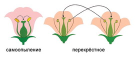
Семя – орган полового размножения и расселения растений: наружи у семян имеется плотный покров – кожура...
История создания датчика движения: Первый прибор для обнаружения движения был изобретен немецким физиком Генрихом Герцем...
Семя – орган полового размножения и расселения растений: наружи у семян имеется плотный покров – кожура...
Топ:
Устройство и оснащение процедурного кабинета: Решающая роль в обеспечении правильного лечения пациентов отводится процедурной медсестре...
Установка замедленного коксования: Чем выше температура и ниже давление, тем место разрыва углеродной цепи всё больше смещается к её концу и значительно возрастает...
Проблема типологии научных революций: Глобальные научные революции и типы научной рациональности...
Интересное:
Распространение рака на другие отдаленные от желудка органы: Характерных симптомов рака желудка не существует. Выраженные симптомы появляются, когда опухоль...
Что нужно делать при лейкемии: Прежде всего, необходимо выяснить, не страдаете ли вы каким-либо душевным недугом...
Национальное богатство страны и его составляющие: для оценки элементов национального богатства используются...
Дисциплины:
|
из
5.00
|
Заказать работу |
Содержание книги
Поиск на нашем сайте
|
|
|
|
Word List:
| 1. ductility | пластичность |
| 2. service life | эксплуатационный ресурс, срок службы |
| 3. fatigue cracks | трещины, вызванные усталостью материала |
| 4. crack path | ход трещин |
| 5. stress | напряжение |
| 6. creep-fatigue | крип-усталость; ползучесть в сочетании с усталостью |
| 7. grain boundary | граница между гранулами, волокнами |
| 8. corroboration | подтверждение теории |
| 9. finite-element | конечный элемент |
| 10. integrity | целостность |
| 11. tensile stress | напряжение при растяжении |
| 12. fretting fatigue to fret | Фреттинг-усталость изнашивать, разъедать, вызывать коррозию |
| 13.initiation site | место зарождения трещины |
| 14. a series of straight extensions | серия прямолинейных удлинений трещин в ходе эксперимента |
| 15. infinitesimal | бесконечно малая (величина) |
| 16. curvilinear | криволинейный |
| 17. incremental changes | увеличение роста трещины |
Fatigue Cracks in Turbine Discs
The structural integrity of turbine disc components is dependent upon the initiation and growth of fatigue cracks. Countermeasures such as careful material selection aim to minimize crack growth but the probability of fatigue failure remains whilst materials such as nickel-based superalloys used to manufacture turbine discs have some ductility. To calculate the service life of each component of the turbine disc requires knowledge of the probable crack path(s) and the stress intensity factors associated with them. The use of techniques that provide engineers with this information at the design stage will encourage the development of components with higher structural integrity.
One of the principal experimental methods of stress analysis available to the design engineer is photoelasticity. This can be used to perform independent stress analyses or for corroboration of finite-element results. The determination of stress intensity factors using two-dimensional photoelasticity has almost been fully optimized. Techniques that predict the directions of crack growth have also been developed in line with the need to assess the likely mode of failure, particularly in aircraft structures.
Fatigue crack growth at the high temperatures existing in turbines is a complex interaction between the mechanisms of creep-fatigue, grain boundarymicrostructure and the operating environment. To enable predictions to be made of fatigue crack paths in any component requires information regarding initiation sites and the mechanism by which the crack propagates which are influenced by the state of stress at the crack tip and the associated behaviour of the material.
Although crack initiation has been reported to involve a number of complex processes, only the initiation site is required to determine the crack path. Typically, initiation occurs at locations of highest tensile stress at a boundary or within regions of contact where the crack is developed through the process of fretting fatigue.
The photoelastic prediction of the fatigue crack path is constructed from a series of straight extensions made to the experimental crack whereas the real fatigue crack grows in infinitesimal extensions following a curvilinear path. The error incurred here is minimized as the incremental changes in direction of the predicted crack path are restricted to be less than 5-10°.
In modelling a turbine disc the degree of accuracy of test results depends on how well the prototype material compares with the photoelastic material.
Focused Practice
I. Answer the following questions:
1. What does the structural integrity of turbine disc components
depend on?
2. What knowledge is required to calculate the service life of each component of the turbine disc?
3. What can photoelasticity be used for?
4. Why have techniques that predict the directions of crack growth been developed?
5. Where does crack initiation occur?
6. What is the photoelastic prediction of the fatigue crack path constructed from?
II. Analyse the grammar structures underlined in the above text.
III. Speak on: Fatigue cracks in turbine discs.
Unit 18
Grammar: The Passive Voice
Word List:
| 1. tip seal arrangement | герметичное устройство, кожух |
| 2. forward and rear assemblies | передний и задний блоки (агрегаты) |
| 3. blades | лопатки, лопасти (fixed – неподвижные, moving – движущиеся) |
| 4. bearing housing bearing wall | установочный узел с подшипниками несущая стена |
| 5. casing | кожух, каркас, рама |
| 6. clearance | зазор |
| 7. plenum chamber | нагнетательная камера высокого давления |
| 8. cold setting | холодная обмуровка (на холоде) |
| 9. downstream | нисходящий поток |
| 10. gland | сальник, уплотнитель |
| 11. traverse /traversable probe instruments | зонды (приборы для определения поперечных потоков в лопатках турбины) |
| 12. carrier rings | несущие кольца |
| 13. rack and pinion arrangement | зубчато-реечная передача |
| 14. trailing edge stiffness | жесткость задней кромки |
| 15. split shaft 16. thrust | разъёмный вал осевое давление |
| 17. fitting and removal | сборка и разборка |
| 18. friction and torque load | нагрузка, обусловленная трением и моментом вращения |
| 19. spacing ring | шайба |
| 20. pitch and lean angle | продольный и поперечный крен |
The Split Shaft Design
The turbine casing is divided into structurally independent forward and rear assemblies to suit the split shaft design. Each of the two bladed discs is mounted on its own separate cantilevered shaft system in a manner which allows rapid fitting and removal. The first stage diaphragm and rotor are housed in the forward assembly which is bolted onto the inlet plenum chamber. This assembly also carries the second stage diaphragm since the diaphragm glands of both stages seal against the first stage shaft. The rear assembly, which is mounted on its own foundations, carries the bearing housings and tipseal arrangement for the test stage. Thisavoids any problem with setting and maintaining correct radial clearances which might otherwise arise due to the split shaft arrangement. The abutment between the two assemblies lies between the test stage fixed and moving rows and the rear section can slide axially on its mountings to allow variation of the interspace gap and to provide access for traversable probe instruments. Spacing rings areinserted between the casing sections to form the end wall profile.
The rear assembly can also be removed as a unit to improve access during strip and rebuild operations.
Special moulding techniques have been developed to produce low cost plastic fixed blades with steel reinforcements to provide adequate trailing edge stiffness and overall diaphragm strength. Cold setting plastics are also used in the construction of model diaphragms to retain the fixed blades at the precise chosen settings of stagger, pitch and lean angle. After test the diaphragms can be readily dismantled and the blades reused in later test configurations.
Radially adjustable rollers support the test stage diaphragm in order to allow the fixed blades to be indexed past the traverse probe instruments at the moving blade inlet and outlet planes. Traverse probe instruments at the stage inlet plane are held in the rotatable diaphragm and are thus traversed circumferentially through the wakes from the first stage fixed blades. The diaphragm rotational movement is effected through a rack and pinion arrangement.
An air bearing on the downstream face of the diaphragm carrier ring is pressurized during rotation to lift the diaphragm axially against the aerodynamic thrust to reduce friction and torque load.
Focused Practice
I. Answer the following questions:
1. Why is the turbine casing divided into structurally independent forward and rear assemblies?
2. How is each of the two bladed discs mounted?
3. Where are the first stage diaphragm and rotor housed?
4. What does the rear assembly carry?
5. Where does the abutment between the two assemblies lie?
6. What have special moulding techniques been developed for?
7. Why are cold setting plastics used in the construction of model diaphragms?
II. Analyse the grammar structures underlined in the above text.
III. Speak on: Forward and rear assemblies.
Unit 19
|
|
|

Историки об Елизавете Петровне: Елизавета попала между двумя встречными культурными течениями, воспитывалась среди новых европейских веяний и преданий...
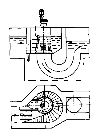
Состав сооружений: решетки и песколовки: Решетки – это первое устройство в схеме очистных сооружений. Они представляют...
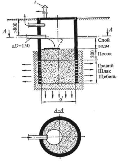
Индивидуальные очистные сооружения: К классу индивидуальных очистных сооружений относят сооружения, пропускная способность которых...
Биохимия спиртового брожения: Основу технологии получения пива составляет спиртовое брожение, - при котором сахар превращается...
© cyberpedia.su 2017-2026 - Не является автором материалов. Исключительное право сохранено за автором текста.
Если вы не хотите, чтобы данный материал был у нас на сайте, перейдите по ссылке: Нарушение авторских прав. Мы поможем в написании вашей работы!

