
История создания датчика движения: Первый прибор для обнаружения движения был изобретен немецким физиком Генрихом Герцем...
Индивидуальные и групповые автопоилки: для животных. Схемы и конструкции...
История создания датчика движения: Первый прибор для обнаружения движения был изобретен немецким физиком Генрихом Герцем...
Индивидуальные и групповые автопоилки: для животных. Схемы и конструкции...
Топ:
Определение места расположения распределительного центра: Фирма реализует продукцию на рынках сбыта и имеет постоянных поставщиков в разных регионах. Увеличение объема продаж...
Организация стока поверхностных вод: Наибольшее количество влаги на земном шаре испаряется с поверхности морей и океанов...
Особенности труда и отдыха в условиях низких температур: К работам при низких температурах на открытом воздухе и в не отапливаемых помещениях допускаются лица не моложе 18 лет, прошедшие...
Интересное:
Подходы к решению темы фильма: Существует три основных типа исторического фильма, имеющих между собой много общего...
Что нужно делать при лейкемии: Прежде всего, необходимо выяснить, не страдаете ли вы каким-либо душевным недугом...
Мероприятия для защиты от морозного пучения грунтов: Инженерная защита от морозного (криогенного) пучения грунтов необходима для легких малоэтажных зданий и других сооружений...
Дисциплины:
|
из
5.00
|
Заказать работу |
|
|
|
|
General
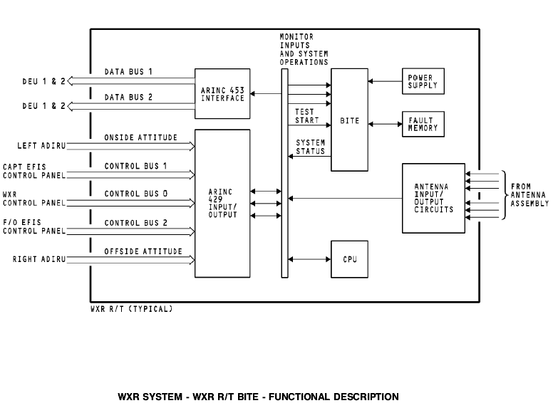
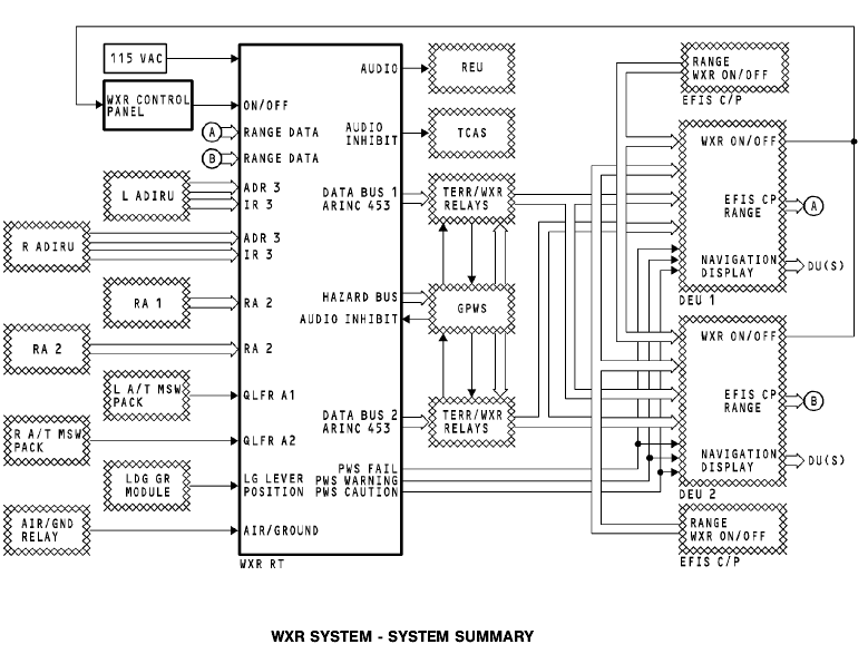
The CPU in the WXR R/T controls the operation of the BITE module. These are the functions of the BITE module:
· Gets status information from the interface components
· Gets internally monitored data
· Does a self-test when it gets a command from the WXR CP
· Sends a test pattern to the DEUs to show on the ND
· Sends system status data to the DEUs to show on the ND.
Internal Input Monitoring
The BITE monitors these things:
· Over temperature from the power supply
· Control and range from the WXR panel on control bus 0
· Range inputs from the EFIS control panels on control bus 1 and 2
· Antenna scan and elevation position from the CPU.
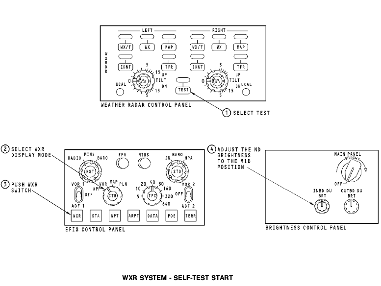
WXR SYSTEM - SELF-TEST START
General
WARNING: DO NOT OPERATE THE WEATHER RADAR WHILE FUEL IS ADDED OR REMOVED FROM THE AIRPLANE. DO NOT TRANSMIT RF ENERGY WHILE FUEL IS ADDED OR REMOVED IN AN AREA 300 FEET OR LESS IN FRONT OF THE ANTENNA. THIS CAN CAUSE AN EXPLOSION.
WARNING: MAKE SURE NO PERSONS ARE IN THE AREA 50 FEET OR LESS FROM THE ANTENNA WHEN IT TRANSMITS RF ENERGY. RF ENERGY CAN CAUSE INJURIES TO PERSONS.
CAUTION: MAKE SURE NO LARGE METALLIC OBJECTS ARE CLOSER THAN 300 FEET FOR THE 180-DEGREE AREA IN FRONT OF THE AIRPLANE WHEN THE RADAR OPERATES. LARGE METAL OBJECTS CAN INCLUDE HANGARS, TRUCKS, OR OTHER AIRPLANES. DAMAGE TO THE TRANSCEIVER COULD OCCUR IF OBJECTS ARE IN THIS AREA. THIS DOES NOT APPLY WHEN THE WEATHER RADAR OPERATES IN THE TEST MODE.
Test Preparation
On the WXR control panel, select these functions:
· Set the mode selector to the TEST position.
· Set the tilt control to 0 degrees.
· Set the gain control to the Auto position.
On the EFIS control panel, select these functions:
· Set the range selector to the 40 NM position.
· Set the mode selector to the correct ND mode (expanded APP, expanded VOR, expanded MAP or centered MAP).
Also, adjust the inner ND brightness control to the middle position.
Test Start
Push the WXR switch on the EFIS control panel to apply power to the WXR R/T.
WXR SYSTEM - SELF-TESTILF
Training Information Point
During a test, the weather radar (WXR) system transmits a few pulses to let the BITE monitor the operation. Do not do a test of the WXR system in a hanger. Make sure the nose of the airplane points away from buildings and other aircraft or large metal objects.
Test Preparation
On the WXR control panel, select these functions:
· Set the mode selector to the WXR position
· Set the tilt control to 0 degrees
· Set the gain control to the AUTO position.
On the EFIS control panel, select these functions:
· Set the range selector to 40 NM
· Set the mode selector to the correct ND mode (expanded
APP, expanded VOR, expanded MAP or centered MAP).
Also, adjust the inner ND brightness control to the middle
|
|
position.
Test Start
On the EFIS control panel, push the WXR switch to apply power to the WXR R/T. On the WXR control panel, set the mode selector to the TEST position to start the test.
NOTE: If the WXR mode selector is in the TEST position before you apply power to the WXR R/T, you must set the mode selector to another mode and then set the mode
selector to TEST to start the test.
Test Operation
During the test, these things happen:
· R/T transmits a few pulses to let the BITE monitor for correct operation
· R/T makes a test pattern and sends it to the DEU to show on the NDs
· R/T sends test messages and mode, gain, and tilt information to the DEUs to show on the NDs
· WXR test pattern shows on ND.
The PWS symbol shows in the TEST pattern. If PWS finds a windshear threat while in TEST mode, the test stops. PWS then shows the actual display data and alert annunications.
The test pattern shows until you select another mode on the WXR panel or EFIS control panel.
Test Pass
For a valid WXR self-test, CDS shows these displays:
· WXR test pattern
· Amber WINDSHEAR message on ND
· Aural message - MONITOR RADAR DISPLAY
· Red WINDSHEAR message on ND and PFD
· Aural message - GO AROUND, WINDSHEAR AHEAD, (pause) WINDSHEAR AHEAD, WINDSHEAR AHEAD
· WXR on alert message line one
· TEST on alert message line two.
Test Fail
For a test that fails, these are the indications on the ND:
· WXR test pattern does not show
· WXR shows on alert message on line one
· FAIL shows on alert message on line two
· Line three shows all of the failures.
These are the messages that can show on line three:
· R/T - receiver/transmitter fault
· ANT - antenna fault
· CONT - control panel fault
· ATT - attitude input fault
· WEAK - calibration fault.
There is no Aural output from WXR if the test fails.
Training Information Point
There are bite instructions to do a manual test of the weather radar in the CDS DEU BITE menu. This test is WXR INTERFACE TEST and shows three pages of instructions. This test is for the CDS/WXR interface. 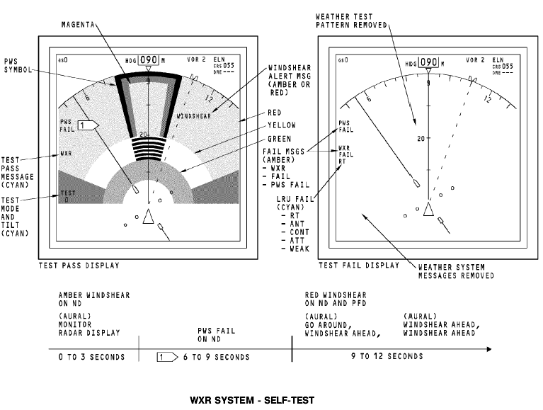
Вопросы для самоконтроля.
1. Назначение, выполняемые функции.
2. Распределение частотного диапазона.
3. Состав типовой МНРЛС.
4. Назначение РЛС «Гроза».
5. Состав РЛС «Гроза».
6. Основные характеристики РЛС «Гроза».
7. Принцип действия.
8. Органы управления и регулировки РЛС «Гроза».
9. Включение, проверка функционирования РЛС «Гроза».
10. Индикация и сигнализация.
11. Какова ДН антенны РЛС «Гроза» в различных режимах на малых дальностях.
12. Какова ДН антенны РЛС «Гроза» в различных режимах на средних дальностях.
13. Какова ДН антенны РЛС «Гроза» в различных режимах на больших дальностях.
14. Какая участок является наиболее опасным в изображении метеообъекта.
15. От чего зависит высота просматриваемого воздушного слоя в режиме «Метео».
|
|
16. Через какое время после включения РЛС нажатием клавиши «РЛС» локатор готов к работе.
17. В каком режиме осуществляется ручное управление сканированием антенны.
18. Из какого режима производится перевод в режим «Снос».
19. Из какого режима производится перевод в режим «Контур».
20.На каком расстоянии должны отсутствовать люди и крупные отражающие строения перед началом проверки РЛС.
21. Чем обеспечивается Формирование антенной узкого или веерного луча.
22. Назначение импульсов бланкирования.
23. Назначение старт-импульсов.
24. Назначение ферритового АП (циркулятора).
25. Назначение схемы ВАРУ.
26. Назначение системы гиростабилизации.
27. Назначение системы АПЧ.
28. Назначение магнетрона.
29. Назначение формирующей линии магнитного модулятора.
30. Какую амплитудную характеристику имеет УПЧ.
28. Какова амплитудная характеристика видеоусилителя в режимах «Земля»,
«Контур» и «Метео».
29. Назначение, состав, основные характеристики WXR В737.
30. Принцип работы WXR В737.
31. Интерфейс WXR В737.
32. Включение, проверка функционирования WXR В737.
Рекомендуемая литература.
Основная
1. Сосновский А.А., Хаймович И.А. Радиоэлектронное оборудование летательных аппаратов. Справочник – М.: Транспорт, 1987г.
2. Учебное пособие. Радиоэлектронное оборудование ЛА. Составитель Кукушин В.А. Академия ГА, 2007г.
3. Учебное пособие. COMMUNICATION СВЯЗНОЕ ОБОРУДОВАНИЕ BOEING 737-600/700/800/900. Training Manual. Составитель Кукушин В.А. Академия ГА, 2008г.
4. Учебное пособие. NAVIGATION. Part 1. НАВИГАЦИОННОЕ ОБОРУДОВАНИЕ. Часть 1. BOEING 737-600/700/800/900. Training Manual. Составитель Кукушин В.А. Академия ГА, 2008г.
5. Учебное пособие. COMMUNICATIONS СВЯЗНОЕ ОБОРУДОВАНИЕ
А-320. Training Manual. Составитель Кукушин В.А.
Дополнительная
1. Aircraft Aerodynamic, Structures and Systems. Module 13: M13.04 Communication Navigation (ATA 23/34); M13.06 Equipment and Furnishings (ATA 25) / EASA Part-66 Training Handbook. – LINK&LEARN Aviation Training GmbH, 2007. – 176 p.
2. Эксплуатационная документация на аппаратуру. (Технические описания. Инструкции по эксплуатации. АММ).
|
|
|
Особенности сооружения опор в сложных условиях: Сооружение ВЛ в районах с суровыми климатическими и тяжелыми геологическими условиями...
Типы сооружений для обработки осадков: Септиками называются сооружения, в которых одновременно происходят осветление сточной жидкости...

Типы оградительных сооружений в морском порту: По расположению оградительных сооружений в плане различают волноломы, обе оконечности...
Состав сооружений: решетки и песколовки: Решетки – это первое устройство в схеме очистных сооружений. Они представляют...
© cyberpedia.su 2017-2024 - Не является автором материалов. Исключительное право сохранено за автором текста.
Если вы не хотите, чтобы данный материал был у нас на сайте, перейдите по ссылке: Нарушение авторских прав. Мы поможем в написании вашей работы!