Purpose
The HF communication transceiver transmits and receives RF signals for voice communication.
Physical Description
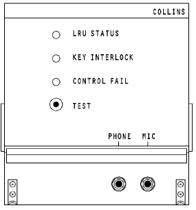
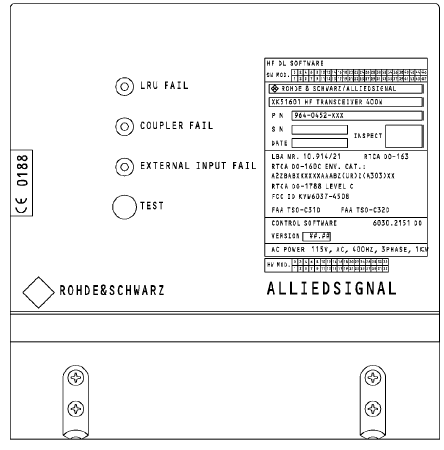
The front panel has these components:
· Three fault LEDs
A TEST push-button
· A microphone jack
· A headphone jack.
All electrical connections are through connectors at the causes the transceiver.
Power
The transceiver must have 115 volts, 400 Hz, 3 phase ac power to operate.
Transceiver RF output is 400 watts peak envelope power (PEP) in the single sideband (SSB) mode. It is 125 watts average in the amplitude modulated (AM) mode. In the AM mode the tranceiver transmits the amplitude modulation equivalent
(AME). AME is the carrier frequency plus the upper side band.
Indications
The LRU STATUS LED comes on red for a failure in the HF transceiver.
The KEY INTERLOCK LED comes on red when the transceiver keys and there is a failure in the HF coupler. Transmission is not possible at this time.
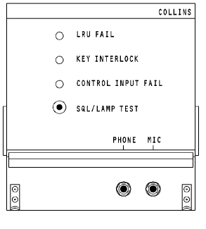
The CONTROL FAIL LED comes on red if there is no input from the control panel or if the control panel input goes invalid.
The COUPLER FAIL LED comes on red when there is a failure in the HF coupler. Transmission is not possible at this time.
The CONTROL INPUT FAIL LED comes on red if there is no input from the control panel or if the control panel input goes invalid.
The EXTERNAL INPUT LED comes on red if there is no input
from the control panel or if the control panel input goes invalid.
ILF 542
BITE
Push the SQL/LAMP TEST push button to stop the operation of the squelch circuit and to hear background noise through the headphones. This test also grounds the RF sensitivity and makes the front panel LEDs come on.
Push the TEST push button to test the transceiver front panel LEDs and to start a self-test. Connect a headphone to the transceiver front panel microphone jack to hear two short tones, and after one second, one additional tone through the audio system.
HF ANTENNA COUPLER
Purpose
The HF antenna coupler matches the transceiver 50 ohm impedance output to the antenna impedance at the set frequency. This decreases the voltage standing wave ratio --уменьш. Коэф. (VSWR) to less than 1.3:1.
Physical Description
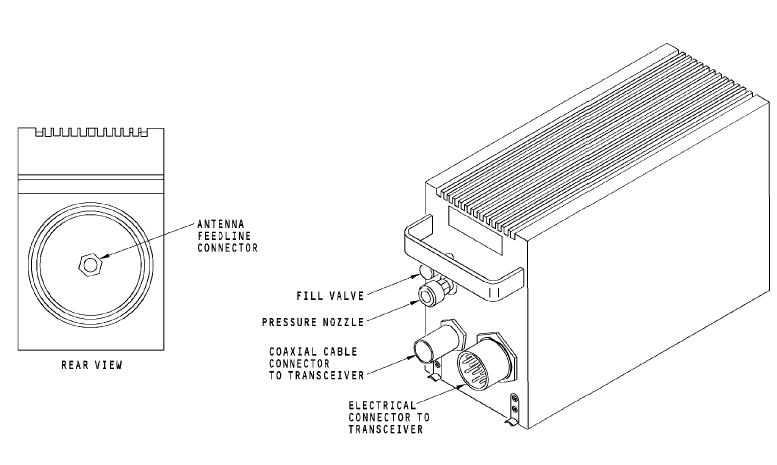
The coupler front panel has these components:
· Electrical connector to transceiver
· Coaxial connector to transceiver
· Pressure nozzle.
· The rear panel has the antenna feedline connector.
Operation
The coupler uses 115v ac to operate. It does not need special cooling.
The coupler tunes in the aeronautical frequency range of 2 to
29.999 MHz. Tuning occurs in 2 to 4 seconds, 7 seconds maximum.
Training Information Point
CAUTION: YOU MUST PREPARE EACH HF COUPLER FOR REMOVAL. IF YOU DO NOT PREPARE FOR THE REMOVAL, YOU CAN CAUSE DAMAGE TO THE INTERNAL PARTS OF THE HF ANTENNA COUPLER.
CAUTION: MOVE THE HF ANTENNA COUPLER CAREFULLY.
SET THE COMPONENT ON ITS BOTTOM. DO NOT SET THE COMPONENT ON ITS END (WITH THE HANDLE UP). INTERNAL PARTS ARE EASILY DAMAGED.
It is important to position the antenna coupler tuning elements to the home position before you move the coupler. This will prevent damage to the coupler internal parts.
HF ANTENNA
Purpose
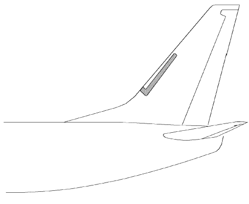
The HF antenna radiates and receives the RF signal.
Physical Description
The HF antenna is a notch type antenna. It is a U- shaped fiberglass material. The antenna is sealed within the leading edge of the vertical stabilizer.
The antenna receives the feed line from the antenna coupler.
WARNING: MAKE SURE PERSONNEL STAY A MINIMUM OF SIX FEET AWAY FROM THE VERTICAL STABILIZER WHEN THE HF SYSTEM TRANSMITS. RF ENERGY FROM THE HF COMMUNICATION ANTENNA CAN CAUSE INJURIES TO PERSONNEL.
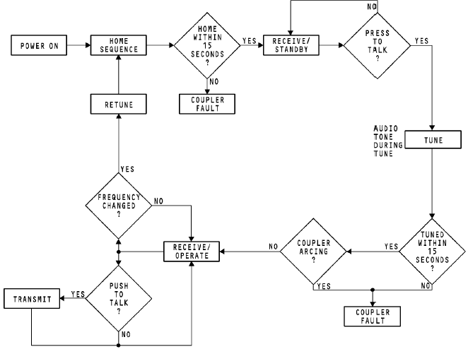
HF FUNCTIONAL MODES
General
The HF communication system uses an antenna coupler to keep a 50 ohm impedance match between the transceiver and the antenna. This impedance match decreases reflected power through the RF output circuit back to the transceiver. The HF communication system uses functional modes to complete the receive, tune, and transmit operation. These are the HF communication system functional modes:
· Home
· Receive/standby
· Tune
· Receive/operate
· Transmit.
The HF system controls the modes in sequence. The modes do --послед-ть, очередность
not change until all necessary conditions for the modes occur. --произошли
Home Mode
The home mode starts at power-up or when a new frequency is set. The transceiver sends a rechannel pulse to the coupler to start the home mode. The antenna tuning elements in the coupler move to the home position. The elements are in a position for minimum attenuation of incoming signals. It is important that the antenna tuning elements inside the coupler be in the home position before you move the coupler. If you move the coupler before the tuning elements are in the home position, damage to internal parts can occur.
Receive/Standby Mode
The receive/standby mode starts when the antenna tuning elements are in the home position. In the receive/standby mode, the HF system can receive RF signals at the set frequency. The system is ready to key for tuning at any time when it receives a PTT from the REU.
Tune
The tune occurs in these steps:
· Tune A (resonance)
· Tune B (load)
· Tune C (VSWR).
To start tune mode A, key the transceiver. The transceiver
microprocessor sets the AM mode and the key is latched. The transceiver sends reduced RF power to the antenna coupler. A 1 kHz tone can be heard at the transceiver mic jack or through the flight interphone system as the tuning occurs.
The antenna coupler tunes in 2 to 4 seconds.
The antenna coupler discriminator circuit operates to set phase differences between the RF voltage and current. The antenna coupler tuning elements are set for zero phase difference.
During tune mode B, tuning elements are set to a total impedance of 50 ohms or less and resonant.
During tune mode C, the tuning elements move so that the RF power load makes a VSWR less than 1.3:1. The reflected power is less than 2 watts RF.
Receive/Operate
The receive/operate mode occurs when tune mode C is complete. The key latch is removed. The tuning RF power from the transceiver is tuned off, and the 1 kHz tone stops. The system is ready for reception or transmission.
Transmit
The pilot keys the microphone to transmit. The coupler adjusts tuning elements to keep VSWR less than 1.3:1 during modulated transmission. The audio tone through the flight interphone system does not sound at this time.