Power
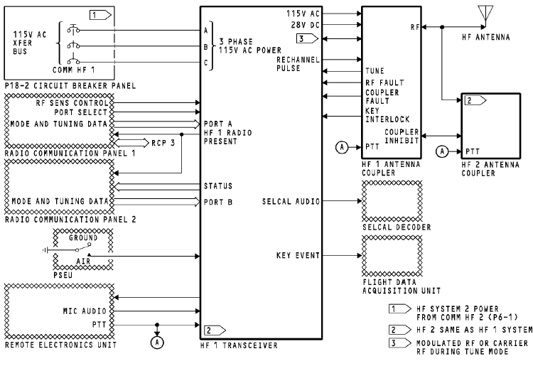
The 115v ac transfer (XFR) bus supplies three-phase power to the HF transceiver.
The transceiver supplies 115v ac and 28v dc power to the HF
antenna coupler.
HF Transceiver
The HF transceiver has an interface with these components:
· RCP 1, 2, and 3
· Selective calling (SELCAL) decoder
· Remote electronics unit (REU)
· HF antenna coupler
· Flight data acquisition unit
· Proximity switch electronics unit (PSEU).
Radio Communication Panel
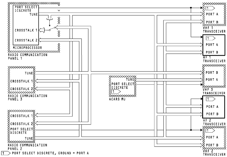
RCP 1 supplies frequency information to the HF 1 transceiver on an ARINC 429 bus to port A and to the HF 2 transceiver on port B. RCP 2 supplies frequency information to the HF 1 transceiver on an ARINC 429 bus to port B and to the HF 2 transceiver on port A. For more information about tuning interfaces, see HF Communication System - Tuning Interfaces.
The HF transceiver supplies the condition of the transceiver to the radio communication panels. The condition of the transceiver is one of the two: OK or FAILED.
The radio communication panel supplies these to the HF transceiver:
· Amplitude modulated or single side-band control
· Tuning data
· Port select discrete.
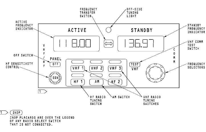
RADIO COMMUNICATION PANEL
Antenna Couplers
The antenna couplers supply these to the transceivers:
· Key interlock
· Tune in progress
· Received RF
· RF fault
· Coupler fault.
The antenna coupler opens the key interlock discrete to stop the transceiver transmit mode. The coupler sends the tune in progress discrete to request tuning power from the transceiver. The RF fault is sent to the transceiver when the coupler detects a fault external to the coupler. The coupler sends the coupler fault discrete to the transceiver when it detects an internal failure.
Received RF from the antenna is sent to the transceiver during receive mode.
The antenna couplers share one common HF antenna. During the transmit mode,
only one coupler has an electrical interface with the antenna. The on-side coupler sends the off-side coupler an inhibit discrete to prevent the off-side radio from transmitting. The couplers supply transmitted RF to theantenna.
They receive push-to-talk (PTT) from the REU to enable the the coupler tune mode.
The HF transceiver supplies these to the antenna coupler:
· Transmitted RF
· RF carrier during tune mode
· Rechannel pulse.
Modulated RF is sent to the antenna through the antenna coupler to be ransmitted. During tune mode, a low wattage RF carrier signal is sent to the coupler to match impedance between the transceiver and the antenna. The transceiver
sends the rechannel pulse to start the coupler home sequence mode.
HF Antenna
The HF antenna receives an RF signal from the antenna coupler and transmits the RF signal to other airplane and ground HF communication systems. The antenna also receives incoming RF signals and sends the RF signals to the antenna coupler.
External Interfaces
The HF transceiver has an interface with these components from other airplane systems:
· Remote electronics unit (REU)
· Selective calling (SELCAL) decoder
· Flight data acquisition unit
· PSEU.
The remote electronics unit sends flight crew microphone (mic) audio to the transceiver to be transmitted. It also sends a PTT to start the transceivers transmit mode. The transceiver sends side tone and received audio to the REU for the flight interphone system.
The transceiver sends received audio to the SELCAL decoder.
The SELCAL decoder isolates the SELCAL code from voice audio.
The flight data acquisition unit receives a PTT from the transceiver for key event marking.
The PSEU tells the HF transceiver whether the airplane is on the ground or in the air.
TUNING INTERFACES
General
The HF communication system uses data buses to share tuning information between the radio communication panels (RCPs) and the communication transceivers.
Tuning Bus
Each RCP has one ARINC 429 output bus.
The RCPs send tuning data to the communication transceivers.
Any RCP can tune any transceiver.
Each RCP sends tuning data and status to the other radio communication panels. This keeps the tuning data synchronized and lets any RCP tune any transceiver.
The RCP keeps the tuning data in memory. Usually, the RCP uses the tuning data from its memory to send on the output bus.
The RCP connects the CROSSTALK 1 bus directly to the output bus. This occur s for these RCP conditions:
RCP does not have power
· RCP is OFF
· RCP is failed.
Port Select Discrete
RCP 1 and 2 send the port select discretes to the transceivers. Each transceiver has two tuning data input ports, port A and port B. The transceiver uses the port select discrete to select the input port. A grounded port select discrete causes the transceiver to use port A. An open port select discrete causes the transceiver to use port B.
Training Information Point
If RCP 1 fails, you can tune the HF 1 transceiver with RCP 2 or 3. RCP 1 port select discrete changes from ground to open, and RCP 2 sends tuning data to input port B. RCP 3 sends tuning data on CROSSTALK 2 bus which is connected to RCP 2. RCP 2 connects this tuning data to the output TUNE bus.
If RCP 2 fails, you can tune the HF 2 transceiver with RCP 1 or 3. RCP 2 port select discrete changes from ground to open, and RCP 1 sends tuning data to input port B. RCP 3 sends tuning data on CROSSTALK 1 bus which is connected to RCP 1. RCP 1 connects this tuning data directly to the output TUNE bus.