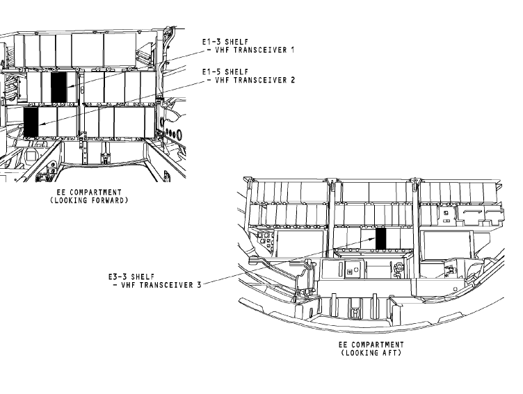
VHF transceiver 1 is on the E1-3 shelf.
VHF transceiver 2 is on the E1-5 shelf.
VHF transceiver 3 is on the E3-3 shelf.
General
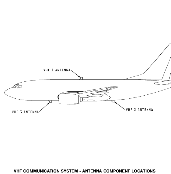
The VHF antennas are on the top and the bottom of the airplane fuselage on the centerline.
Power
The 28v dc standby bus supplies power to the VHF 1 transceiver and radio communication panel (RCP) 1.
VHF 1 Transceiver
The VHF 1 transceiver has an interface with these components:
· RCP 1, 2, and 3
· VHF antenna
· Proximity switch electronics unit
· Remote electronics unit
· SELCAL decoder unit
· Flight data acquisition.
Radio Communication Panel
RCP 1 supplies frequency information to the VHF 1 transceiver on an ARINC 429 bus to port A. RCP 2 supplies frequency information to the VHF 1 transceiver on an ARINC 429 bus to port B. RCP 3 can supply frequency data to the VHF 1 transceiver through RCP 1 or 2. For more information about tuning interfaces, see VHF Communication System - Tuning Interfaces.
The VHF transceiver supplies the status of the transceiver to the RCPs.
VHF Antenna
The VHF antenna receives an RF signal from the VHF transceiver and transmits the RF signal to other airplane and ground VHF communication systems. The antenna also receives incoming RF signals and sends the RF signals to the VHF transceiver. The transceiver demodulates or detects the audio from the RF carrier signal.
External Interfaces
The VHF 1 transceiver has an interface with components from other airplane systems.
The proximity switch electronic unit sends a ground signal to increase t he flight leg count to track fault history. Увеличение расширение
The remote electronics unit sends flight crew microphone (mic) audio to the transceiver to be transmitted. It also sends a PTT to start the transceiver transmit mode. The transceiver sends side tone and received audio to the REU for the flight interphone system.
The transceiver sends received audio to the SELCAL decoder. The SELCAL decoder isolates the SELCAL code from voice audio.
The flight data acquisition unit receives a PTT from the transceiver for key event marking. 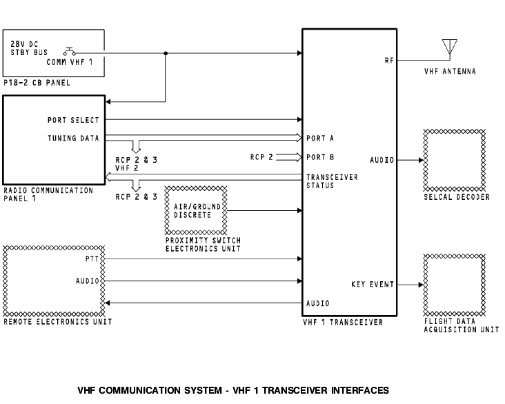
Power
The dc bus 2 supplies 28v dc power to the VHF 2 transceiver and radio communication panel (RCP) 2.
VHF 2 Transceiver
The VHF 2 transceiver has an interface with these components:
· RCP 1, 2, and 3
· VHF antenna
· Proximity switch electronics unit
· Remote electronics unit
· SELCAL decoder unit
· Flight data acquisition.
Radio Communication Panel
RCP 2 supplies frequency information to the VHF 2 transceiver on an ARINC 429 bus to port A. RCP 1 supplies frequency information to the VHF 2 transceiver on an ARINC 429 bus to port B. RCP 3 can supply frequency data to VHF 2 transceiver through RCP 1 or 2. For more information on tuning interfaces, see VHF Communication System - Tuning Interfaces.
The VHF transceiver supplies the status of the transceiver to the RCPs.
VHF Antenna
The VHF antenna receives an RF signal from the VHF transceiver and transmits the RF signal to other airplane and ground VHF communication systems. The antenna also receives incoming RF signals and sends the RF signals to the VHF transceiver. The transceiver demodulates or detects the audio from the RF carrier signal.
External Interfaces
The VHF 2 transceiver has an interface with components from other airplane systems.
The proximity switch electronic unit sends a ground signal to increase the flight leg count to track fault history.
The remote electronics unit sends flight crew audio to the
transceiver to be transmitted. It also sends a PTT start the
transceiver transmit mode. The transceiver sends side tone and received audio to the REU for the flight interphone system.
The transceiver sends received audio to the SELCAL decoder. The SELCAL decoder isolates the SELCAL code from voice audio.
The flight data acquisition unit receives a PTT from the
transceiver for key event marking. 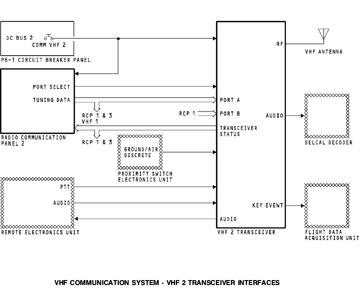
Power
The DC bus 2 supplies 28v dc power to the VHF 3 transceiver and radio communication panel (RCP) 3.
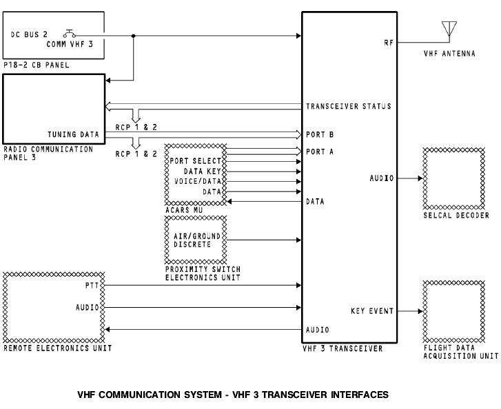
VHF 3 Transceiver
The VHF 3 transceiver has an interface with these components:
· RCP 1, 2, and 3
· VHF antenna
· Proximity switch electronics unit
· Remote electronics unit
· SELCAL decoder unit
· ACARS management unit
· Flight data acquisition unit.
Radio Communication Panel
RCP 3 supplies frequency information to the VHF 3 transceiver on an ARINC 429 bus to port B. The ACARS management unit (MU) sends tuning information to VHF 3 transceiver on an ARINC 429 bus to port A. For more information on tuning interfaces see VHF Communication System - Tuning Interfaces.
The VHF transceiver supplies the status of the transceiver to the RCPs.
VHF Antenna
The VHF antenna receives an RF signal from the VHF
transceiver and transmits the RF signal to other airplane and
ground VHF communication systems. The antenna also
receives RF signals and sends the RF signals to the VHF
transceiver. The transceiver demodulates or detects the audio from the RF carrier signal.
External Interfaces
The VHF 3 transceiver has an interface with components from other airplane systems.
The proximity switch electronic unit sends a ground signal to increase the flight leg count to track fault history.
The remote electronics unit sends flight crew audio to the transceiver to be transmitted. It also sends a PTT to start the transceivers transmit mode. The transceiver sends received audio to the REU for the flight interphone system.
The transceiver sends received audio to the SELCAL decoder. The SELCAL decoder isolates the SELCAL code from voice audio.
The ACARS management unit sends these discrete signals to the VHF 3 transceiver:
· Port select discrete to set the tuning data source
· Data key to give a PTT signal
· Voice/data to set transceiver voice or data mode.
The ACARS management unit sends data audio to the VHF 3 transceiver to be transmitted to the ground station. The VHF 3 transceiver sends received data audio to the ACARS management unit.
The flight data acquisition unit receives a PTT from the
transceiver for key event marking.
 General
The VHF communication system uses data buses to share tuning information between the radio communication panels (RCPs) and the communication transceivers.
Tuning Bus
Each RCP has one ARINC 429 output bus.
The RCPs send tuning data to the communication transceivers.
Any RCP can tune any transceiver.
Each RCP sends tuning data and status to the other radio
communication panels. This keeps the tuning data
synchronized and lets any RCP tune any transceiver.
The RCP keeps the tuning data in memory. Usually, the RCP uses the tuning data from its memory to send on the output bus. The RCP can connect the CROSSTALK 1 bus directly to the output bus. This occurs for these RCP conditions:
· RCP does not have power
· RCP is OFF
· RCP is failed.
Port Select Discrete
RCP 1 and 2 send the port select discretes to the transceivers.
The ACARS MU sends a port select discrete to the VHF 3
transceiver.
The RCPs send the voice/data protect discrete to the VHF 3 transceiver. This discrete selects either the ACARS management unit or the RCPs to tune the VHF 3 transceiver.
Each transceiver has two tuning data input ports, port A and port B. The transceiver uses the port select discrete to select the input port. A grounded port select discrete causes the transceiver to use port A. An open port select discrete causes the transceiver to use port B.
Training Information Point
These are the RCP VHF radio selections when the airplane receives power and there are no RCP faults:
· RCP 1 - VHF 1
· RCP 3 - VHF 3
· RCP 2 - VHF 2.
If RCP 1 fails, you can tune the VHF 1 transceiver with RCP 2 or 3. RCP 1 port select discrete changes from ground to open, and RCP 2 sends tuning data to input port B. RCP 3 sends tuning data on CROSSTALK 2 bus which connects to RCP 2. RCP 2 sends this tuning data to the VHF 1 transceiver on the output TUNE bus.
If RCP 2 fails, you can tune the VHF 2 transceiver with RCP 1 or 3. RCP 2 port select discrete changes from ground to open, and RCP 1 sends tuning data to input port B. RCP 3 sends tuning data on CROSSTALK 1 bus which connects to RCP 1. RCP 1 sends this tuning data to the VHF 2 transceiver on the output TUNE bus.
If RCP 3 fails, you can tune the VHF 3 transceiver with RCP 1 or 2. RCP 1 sends tuning data to RCP 2 on CROSSTALK 1 bus. RCP 2 puts RCP 1 tuning data on the output TUNE bus. RCP 2 output TUNE bus is connected to RCP 3 CROSSTALK 1 bus. The bus relay in RCP 3 is closed. The tuning data connects directly to the output TUNE bus and goes to the VHF 3 transceiver. RCP 2 tuning data goes to the RCP 3 CROSSTALK 1 bus and to VHF 3 transceiver on the output TUNE bus.

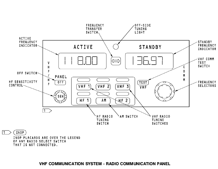
General
The radio communication panel (RCP) provides these functions:
· VHF and HF radio selection
· Active/standby frequency selection
· HF sensitivity control
· Test initiation to the VHF transceiver
· Mode selection to the HF transceiver
· Off switch.
Controls and Indicators
Any radio communication panel can control any transceiver. Push the radio tuning switch to select the transceiver for that radio communication panel. The light above the switch comes on. Each radio communication panel can tune only one transceiver at a time. неглавный
When you select an off-side radio, two off-side tuning lights come on. One light is on the radio communication panel that you use to make the selection. This is the off-side radio. The other light is on radio communication panel of the radio you select. This is the on-side radio.
Set the frequency in the standby frequency indicator. Turn the
frequency selectors to set the frequency. The first digit is always цифра символ -- 1.
The outer knob sets the second two digits (10 MHz and 1MHz) in 1 MHz increments. The inner knob sets the fourth, fifth, and sixth digits (100 kHz, 10 kHz, and 1 kHz) in 25 kHz increments. Внешний наружный ручка головка кнопка шаг приращение
Push the frequency transfer switch to change the active and standby frequencies.
The HF SENS control sets the RF sensitivity level of the HF transceiver. Rotate the control to adjust the sensitivity of the HF transceiver. The inactive frequency indicator shows a value between 0 and 99. Maximum sensitivity is 99. Minimum sensitivity is 0. After a delay, the inactive frequency indicator shows the inactive frequency again.
The VHF communication test switch starts a confidence check of the VHF transceiver. Push the VHF communication test switch to stop the squelch in the VHF transceiver. You hear static when you push the switch. Помехи сх. Бесшумной настройки
Push the OFF switch to stop the operation of the radio communication panel. The switch shows white when it is off.
BITE
The radio communication panel continuously does a self-test. The frequency indicators show PANEL FAIL when there is an internal failure of the radio communication panel.
Purpose
The purpose of the VHF transceiver is to transmit and receive information.
Physical Description
The transceiver is a solid state device. It has these components: устройство схема
· Power supply
· Frequency synthesizer
· Receiver
· Modulator
· Transmitter
· Microprocessor.
Functional Description
The transceiver has these properties:
· 118.000 to 136.975 MHz frequency range
· Voice or data operation
· 25 watts output power
· Built-in fault detection and memory.
Power
The transceiver operates with +27.5v dc.
Controls, Indicators, and BITE
Push the TEST switch to start a system self-test. This includes these tests:
· Transceiver self-test
· Input serial tuning word test последовательный периодический
· Antenna VSWR test.
The front panel LEDs show the results of the VHF system selftest.
These are the front panel LEDs:
· LRU
· CONTROL
· ANTENNA.
The LRU LED shows a failure of the transceiver. The CONTROL LED shows a failure of the ARINC 429 input. The ANTENNA LED shows a failure of the antenna.
All LEDs come on red for three seconds. Then the LRU LED changes to green and the other LEDs stay red for three seconds. Then the LRU LED comes on green for 30 seconds and the CONTROL and ANTENNA LEDs go off.
The LRU LED comes on red after the self-test if there is a
transceiver failure.