
Индивидуальные и групповые автопоилки: для животных. Схемы и конструкции...

Папиллярные узоры пальцев рук - маркер спортивных способностей: дерматоглифические признаки формируются на 3-5 месяце беременности, не изменяются в течение жизни...
Индивидуальные и групповые автопоилки: для животных. Схемы и конструкции...
Папиллярные узоры пальцев рук - маркер спортивных способностей: дерматоглифические признаки формируются на 3-5 месяце беременности, не изменяются в течение жизни...
Топ:
Особенности труда и отдыха в условиях низких температур: К работам при низких температурах на открытом воздухе и в не отапливаемых помещениях допускаются лица не моложе 18 лет, прошедшие...
Оценка эффективности инструментов коммуникационной политики: Внешние коммуникации - обмен информацией между организацией и её внешней средой...
История развития методов оптимизации: теорема Куна-Таккера, метод Лагранжа, роль выпуклости в оптимизации...
Интересное:
Отражение на счетах бухгалтерского учета процесса приобретения: Процесс заготовления представляет систему экономических событий, включающих приобретение организацией у поставщиков сырья...
Принципы управления денежными потоками: одним из методов контроля за состоянием денежной наличности является...
Как мы говорим и как мы слушаем: общение можно сравнить с огромным зонтиком, под которым скрыто все...
Дисциплины:
|
из
5.00
|
Заказать работу |
|
|
|
|
Transformers are devices that transfer energy from one circuit to another by means of a common magnetic field. In all cases except autotransformers, there is no direct electrical connection from one circuit to the other.
When an alternating current flows in a conductor, a magnetic field exists around the conductor. If another conductor is placed in the field created by the first conductor such that the flux lines link the second conductor, then a voltage is induced into the second conductor. The use of a magnetic field from one coil to induce a voltage into a second coil is the principle on which transformer theory and application is based.
Some small transformers for low power applications are constructed with air between the two coils. Such transformers are inefficient because the percentage of the flux from the first coil that links the second coil is small. The number of turns can be increased to increase the voltage output, but this will increase costs. The need then is to increase the amount of flux from the first coil that links the second coil.
The ability of iron or steel to carry magnetic flux is much greater than air. This ability to carry flux is called permeability. Modern electrical steels have permeabilities on the order of 1500 compared to 1.0 for air. This means that the ability of a steel core to carry magnetic flux is 1500 times that of air. Steel cores were used in power transformers when alternating current circuits for distribution of electrical energy were first introduced. When two coils are applied on a steel core almost 100% of the flux from coil 1 circulates in the iron core so that the voltage induced into coil 2 is equal to the coil 1 voltage if the number of turns in the two coils are equal.
Since the permeability of the steel is very high compared to air, all of the flux can be considered as flowing in the steel and is essentially of equal magnitude in all parts of the core.
Equivalent Circuit of an Iron Core Transformer
When voltage is applied to the exciting or primary winding of the transformer, a magnetizing current flows in the primary winding. This current produces the flux in the core. The flow of flux in magnetic circuits is analogous to the flow of current in electrical circuits.
When flux flows in the steel core, losses occur in the steel. There are two components of this loss which are termed “eddy” and “hystersis” losses. The hystersis loss is caused by the cyclic reversal of flux in the magnetic circuit. The eddy loss is caused by the flow of flux normal to the width of the core.
If a solid core were used in a power transformer, the losses would be very high and the temperature would be excessive. For this reason, cores are laminated from very thin sheets such as 0.23 mm and 0.28 mm to reduce the losses. Each sheet is coated with a very thin material to prevent shorts between the laminations. Improvements made in electrical steels over the past 50 years have been the major contributor to smaller and more efficient transformers. Some of the more dramatic improvements are as follows:
|
|
• Development of grain-oriented electrical steels in the mid-1940s.
• Introduction of thin coatings with good mechanical properties.
• Improved chemistry of the steels.
• Introduction of laser scribed steels.
• Further improvement in the orientation of the grains.
• Continued reduction in the thickness of the laminations to reduce the eddy loss component of the core loss.
The combination of these improvements has resulted in electrical steels having less than 50% of the no load loss and 30% of the exciting current that was possible in the late 1940s.
The current to cause rated flux to exist in the core is called the magnetizing current. The magnetizing circuit of the transformer can be represented by one branch in the equivalent circuit shown in Fig. 2.

Fig. 2.
The core losses are represented by [Xr], and the excitation characteristics by [Xm].
When the magnetizing current, which is about 0.5% of the load current, flows in the primary winding, there is a small voltage drop across the resistance of the winding and a small inductive drop across the inductance of the winding. We can represent these voltage drops as Rl and Xl in the equivalent circuit.
However, these drops are very small and can be neglected in the practical case. Since the flux flowing in all parts of the core is essentially equal, the voltage induced in any turn placed around the core will be the same. This results in the unique characteristics of transformers with steel cores. Multiple secondary windings can be placed on the core to obtain different output voltages. Each turn in each winding will have the same voltage induced in it.
1. Read and translate the text.
2. Read the text again and number the points of the plan in the correct order.
1) Advance in electrical steels
2) The magnetizing circuit of the transformer
3) Air Core Transformer
4) The role of a magnetic field in the operation of a transformer
5) The permeability of the steel and iron
6) Losses occurring in the steel
3. Answer the following questions to the text:
1) How is energy transferred between circuits of a transformer?
2) What creates a magnetic field in a conductor?
3) What is the most common material for transformers core? Why?
4) What is permeability?
5) What are the causes of loss in steel?
6) Why is core made laminated?
7) What kind of circuit is called equivalent?
4. Find synonyms.
| 1) flux | a) utilization |
| 2) application | b) similar |
| 3) magnetize | c) decrease |
| 4) turn | d) flow |
| 5) equivalent | e) loop |
| 6) laminate | f) decline |
| 7) reduce | g) coat |
| 8) drop | h) attract |
5. Complete the table below, using a dictionary.
| VERB | NOUN | ADJECTIVE |
| reduction | ||
| induce | ||
| connection | ||
| transformable | ||
| magnet | ||
| thicken | ||
| lamination |
6. Speak on the efficiency of different types of transformers.
TEXT 9. Power Transformers
A transformer has been defined by ANSI/IEEE as a static electrical device, involving no continuously moving parts, used in electric power systems to transfer power between circuits through the use of electromagnetic induction. The term power transformer is used to refer to those transformers used between the generator and the distribution circuits and are usually rated at 500 kVA and above. Power systems typically consist of a large number of generation locations, distribution points, and interconnections within the system or with nearby systems, such as a neighboring utility. The complexity of the system leads to a variety of transmission and distribution voltages. Power transformers must be used at each of these points where there is a transition between voltage levels.
|
|
Power transformers are selected based on the application, with the emphasis towards custom design being more apparent the larger the unit. Power transformers are available for step-up operation, primarily used at the generator and referred to as generator step-up (GSU) transformers, and for step-down operation, mainly used to feed distribution circuits. Power transformers are available as a single phase or three phase apparatus.
The construction of a transformer depends upon the application, with transformers intended for indoor use primarily dry-type but also as liquid immersed and for outdoor use usually liquid immersed.
In the U.S., transformers are rated based on the power output they are capable of delivering continuously at a specified rated voltage and frequency under “usual” operating conditions without exceeding prescribed internal temperature limitations. Insulation is known to deteriorate, among other factors, with increases in temperature, so insulation used in transformers is based on how long it can be expected to last by limiting operating temperatures. The temperature that insulation is allowed to reach under operating conditions essentially determines the output rating of the transformer, called the kVA rating. Standardization has led to temperatures within a transformer being expressed in terms of the rise above ambient temperature, since the ambient temperature can vary under operating or test conditions. Transformers are designed to limit the temperature based on the desired load, including the average temperature rise of a winding, the hottest spot temperature rise of a winding, and, in the case of liquid-filled units, the top liquid temperature rise. To obtain absolute temperatures from these values, simply add the ambient temperature.
The normal life expectancy of power transformers is generally assumed to be about 30 years of service when operated within their ratings; however, they may be operated beyond their ratings, overloaded, under certain conditions with moderately predictable “loss of life”. Situations that may involve operation beyond rating are emergency re-routing of load or through-faults prior to clearing.
Power transformers have been loosely grouped into three market segments based upon size ranges.
These three segments are:
1. Small power transformers 500 to 75001 kVA
2. Medium power transformers 75001 to 100 MVA
3. Large power transformers 100 MVA and above
It was noted that the transformer rating is based on “usual” service conditions, as prescribed by standards. Unusual service conditions may be identified by those specifying a transformer so that the desired performance will correspond to the actual operating conditions. Unusual service conditions include, but are not limited to, the following: high (above 40°C) or low (below –20°C) ambient temperatures; altitudes above 3300 ft above sea level; seismic conditions; and loads with harmonic content above
0.05 per unit.
Efficiency and Losses
Power transformers are very efficient pieces of equipment with efficiencies typically above 99%. The efficiency is derived from the rated output and the losses incurred in the transformer. The basic relationship for efficiency is the output over the input that will generally decrease slightly with increases in load. Total losses are the sum of the no-load and load losses.
|
|
The no-load losses are essentially the power required to keep the core energized, and so are many times referred to as the core losses. They exist whenever the unit is energized. No-load losses depend primarily upon the voltage and frequency, so under operational conditions it will only vary slightly with system variations. Load losses, as the terminology might suggest, result from load currents flowing through the transformer. The two components of the load losses are the I2R losses and the stray losses. I2R losses are based on the measured DC resistance, the bulk of which is due to the winding conductors, and the current at a given load. The stray losses are a term given to the accumulation of the additional losses experienced by the transformer, which includes winding eddy losses and losses due to the effects of leakage flux entering internal metallic structures. Auxiliary losses refer to the power required to run auxiliary cooling equipment, such as fans and pumps, and are not typically included in the total losses as defined above.
1. Read and translate the text.
2. Answer the following questions to the text:
1) How is transformer defined?
2) In what cases are power transformers needed?
3) What does the construction of a transformer depend upon?
4) How is the output rating of the transformer connected with the temperature of insulation?
5) In what cases can power transformer be operated beyond their ratings?
6) What do load losses result from?
3. Find English equivalents of the following phrases in the text
Распределительная сеть, электромагнитная индукция, повышающий трансформатор, однофазный, напряжение в линии электропередачи, величина отдаваемой мощности, трансформатор, заполненный жидким диэлектриком, ожидаемый срок службы, потери рассеяния, температура окружающего воздуха, рабочий режим.
4. Match the words from the text with their corresponding definitions.
| 1) induction | a) the act or practice of keeping something within certain boundaries |
| 2) limitation | b) the power diminution of a circuit or circuit element |
| 3) indoor | c) The imparting of electricity into one object, not connected, to another by the influence of magnetic fields |
| 4) rate | d) the ratio of the work done or energy developed by a machine, engine, etc., to the energy supplied to it, usually expressed as a percentage |
| 5) loss | e) to estimate the normal capacity or power of |
| 6) load | f) relating to the interior of a building |
| 7) efficiency | g) power output (as of a power plant) or power consumption (as by a device) |
5. Put questions to the underlined words.
1) The construction of a transformer depends upon the application, with transformers intended for indoor use primarily dry-type.
2) Transformers are designed to limit the temperature based on the desired load.
3) The efficiency is derived from the rated output and the losses incurred in the transformer.
4) The normal life expectancy of power transformers is generally assumed to be about 30 years of service when operated within their ratings.
5) Auxiliary losses refer to the power required to run auxiliary cooling equipment, such as fans and pumps, and are not typically included in the total losses as defined above.
6. Can losses influence transformer’s cost? Express your opinion.
|
|
|
Поперечные профили набережных и береговой полосы: На городских территориях берегоукрепление проектируют с учетом технических и экономических требований, но особое значение придают эстетическим...
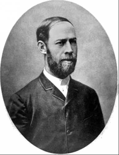
История создания датчика движения: Первый прибор для обнаружения движения был изобретен немецким физиком Генрихом Герцем...
Папиллярные узоры пальцев рук - маркер спортивных способностей: дерматоглифические признаки формируются на 3-5 месяце беременности, не изменяются в течение жизни...
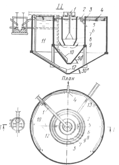
Типы сооружений для обработки осадков: Септиками называются сооружения, в которых одновременно происходят осветление сточной жидкости...
© cyberpedia.su 2017-2024 - Не является автором материалов. Исключительное право сохранено за автором текста.
Если вы не хотите, чтобы данный материал был у нас на сайте, перейдите по ссылке: Нарушение авторских прав. Мы поможем в написании вашей работы!