TEXT 3.Photovoltaics
Silicon PV cells come in several varieties. The most common cell is the single-crystal silicon cell. Other variations include multicrystalline (polycrystalline), thin silicon (buried contact) cells, and amorphous silicon cells.
While single crystal silicon cells are still the most common cells, the fabrication process of these cells is relatively energy intensive, resulting in limits to cost reduction for these cells. Since single-crystal silicon is an indirect bandgap semiconductor (Eg = 1.1 eV), its absorption constant is smaller than that of direct bandgap materials. This means that single-crystal silicon cells need to be thicker than other cells in order to absorb a sufficient percentage of incident radiation.
The cells are assembled into modules, consisting of approximately 33 to 36 individual cells connected in series. Since the open-circuit output voltage of an individual silicon cell typically ranges from 0.5 to 0.6 V, depending upon irradiance level and cell temperature, this results in a module open- circuit voltage between 18 and 21.6 V. The cell current is directly proportional to the irradiance and the cell area. A 4-ft2 (0.372-m2) module (active cell area) under full sun will typically produce a maximum power close to 55 W at approximately 17 V and 3.2 A.
By pouring molten silicon into a crucible and controlling the cooling rate, it is possible to grow multicrystalline silicon with a rectangular cross-section. This eliminates the “squaring-up” process and the associated loss of material. The ingot must still be sawed into wafers, but the resulting wafers completely fill the module. The remaining processing follows the steps of single-crystal silicon, and cell efficiencies in excess of 15% have been achieved for relatively large area cells. Multicrystalline material still maintains the basic properties of single-crystal silicon, including the indirect bandgap.
The current flow direction in most PV cells is between the front surface and the back surface. In the thin silicon cell, a dielectric layer is deposited on an insulating substrate, followed by alternating layers of n- type and p-type silicon, forming multiple pn junctions. Channels are then cut with lasers and contacts are buried in the channels, so the current flow is parallel to the cell surfaces in multiple parallel conduction paths. These cells minimize resistance from junction to contact with the multiple parallel conduction paths and minimize blocking of incident radiation by the front contact. Although the material is not single crystal, grain boundaries cause minimal degradation of cell efficiency. The collection efficiency is very high, since essentially all photon-generated carriers are generated within a diffusion length of a pn junction. This technology is relatively new, but has already been licensed to a number of firms worldwide.
Amorphous silicon has no predictable crystal structure. As a result, the uniform covalent bond structure of single-crystal silicon is replaced with a random bonding pattern with many open covalent bonds. These bonds significantly degrade the performance of amorphous silicon by reducing carrier mobilities and the corresponding diffusion lengths. However, if hydrogen is introduced into the material, its electron will pair up with the dangling bonds of the silicon, thus passivating the material. The result is a direct bandgap material with a relatively high absorption constant. A film with a thickness of a few micrometers will absorb nearly all incident photons with energies higher than the 1.75 eVbandgap energy.
Maximum collection efficiency for a-Si:H is achieved by fabricating the cell with a pin junction. Early work on the cells revealed, however, that if the intrinsic region is too thick, cell performance will degrade over time. This problem has now been overcome by the manufacture of multi-layer cells with thinner pin junctions. In fact, it is possible to further increase cell efficiency by stacking cells of a-SiC:H on top, a-Si:H in the center, and a-SiGe:H on the bottom. Each successive layer from the top has a smaller bandgap, so the high-energy photons can be captured soon after entering the material, followed by middle-energy photons and then lower energy photons.
Gallium arsenide (GaAs), with its 1.43 eV direct bandgap, is a nearly optimal PV cell material. The only problem is that it is very costly to fabricate cells. GaAs cells have been fabricated with conversion efficiencies above 30% and with their relative insensitivity to severe temperature cycling and radiation exposure, they are the preferred material for extraterrestrial applications, where performance and weight are the dominating factors.
Recent advances in III-V technology have produced tandem cells similar to the a-Si:H tandem cell. One cell consists of two tandem GaAs cells, separated by thin tunnel junctions of GaInP, followed by a third tandem GaInP cell, separated by AlInP tunnel junctions.
Another promising thin film material is copper indium (gallium) diselenide (CIGS). While the basic copper indium diselenide cell has a bandgap of 1.0 eV, the addition of gallium increases the bandgap to closer to 1.4 eV, resulting in more efficient collection of photons near the peak of the solar spectrum.
1. Read and translate the text.
2. Read and decide if the following statements are true (T) or false (F).
1). A single-crystal silicon cell is the most widely used cell.
2). The cells are assembled into modules, consisting of approximately 33 to 36 individual cells connected in parallel.
3). Amorphous silicon has predictable crystal structure.
4). With the help of III-V technology tandem cells similar to the a-Si:H tandem cell have been produced.
5). Another promising thin film material is copper indium (gallium) diselenide (CIGS).
3. Findsynonyms.
| limit
| join, link
|
| assemble
| casual
|
| connect
| boundary
|
| degradation
| effectiveness
|
| uniform
| bringtogether
|
| random
| devaluation
|
| absorb
| incorporate
|
| efficiency
| monotonous, invariable
|
4. Complete the table below, using a dictionary.
| VERB
| NOUN (idea)
| NOUN (person)
| ADJECTIVE
|
| -
| -
| -
| intensive
|
| result
| -
| -
| -
|
| grow
| -
| -
| -
|
| -
| resistance
| -
| -
|
| contact
| -
| -
| -
|
| -
| insulation
| -
| -
|
| -
| -
| -
| efficient
|
5. Put the following words in the correct order to form a sentence.
1). Silicon, are, types, cells, there, several, of.
2). Series, are, sometimes, modules, connected, the assembled, cells, into, in.
3). Front, between, is, direction, current, back, surfaces, the, and, the, flow?
6. Write down the characteristic features of four types of Silicon Cells in a given table:
| SingleCrystalSiliconCell
| MulticrystallineSiliconCell
| Thin Silicon (Buried Contact) Cell
| AmorphousSiliconCell
|
|
|
|
|
|
7. Make a written summary (abstract, annotation) to the text.
TEXT 5. Generator
Synchronous generators and induction generators are used to convert the mechanical energy output of the turbine to electrical energy. Induction generators are used in small hydroelectric applications (less than 5 MVA) due to their lower cost which results from elimination of the exciter, voltage regulator, and synchronizer associated with synchronous generators. The induction generator draws its excitation current from the electrical system and thus cannot be used in an isolated power system. Also, it cannot provide controllable reactive power or voltage control and thus its application is relatively limited.
The majority of hydroelectric installations utilize salient pole synchronous generators. Salient pole machines are used because the hydraulic turbine operates at low speeds, requiring a relatively large number of field poles to produce the rated frequency. A rotor with salient poles is mechanically better suited for low-speed operation, compared to round rotor machines which are applied in horizontal axis high-speed turbo-generators.
Generally, hydroelectric generators are rated on a continuous-duty basis to deliver net kVA output at a rated speed, frequency, voltage, and power factor and under specified service conditions including the temperature of the cooling medium (air or direct water). Industry standards specify the allowable temperature rise of generator components (above the coolant temperature) that are dependent on the voltage rating and class of insulation of the windings. Standards also provide guidance on short circuit capabilities and continuous and short-time current unbalance requirements.
Synchronous generators require direct current field excitation to the rotor, provided by the excitation system.
While the generator may be vertical or horizontal, the majority of new installations are vertical. The basic components of a vertical generator are the stator (frame, magnetic core, and windings), rotor (shaft, thrust block, spider, rim, and field poles with windings), thrust bearing, one or two guide bearings, upper and lower brackets for the support of bearings and other components, and sole plates which are bolted to the foundation. Other components may include a direct connected exciter, speed signal generator, rotor brakes, rotor jacks, and ventilation systems with surface air coolers.
The stator core is composed of stacked steel laminations attached to the stator frame. The stator winding may consist of single turn or multi-turn coils or half-turn bars, connected in series to form a three phase circuit. Double layer windings, consisting of two coils per slot, are most common. One or more circuits are connected in parallel to form a complete phase winding. The stator winding is normally connected in wye configuration, with the neutral grounded through one of a number of alternative methods which depend on the amount of phase-to-ground fault current that is permitted to flow. Generator output voltages range from approximately 480 VAC to 22 kVACline-to-line, depending on the MVA rating of the unit. Temperature detectors are installed between coils in a number of stator slots.
The rotor is normally comprised of a spider attached to the shaft, a rim constructed of solid steel or laminated rings, and field poles attached to the rim. The rotor construction will vary significantly depending on the shaft and bearing system, unit speed, ventilation type, rotor dimensions, and characteristics of the driving hydraulic turbine. Damper windings or amortisseurs in the form of copper or brass rods are embedded in the pole faces, for damping rotor speed oscillations.
The thrust bearing supports the mass of both the generator and turbine plus the hydraulic thrust imposed on the turbine runner and is located either above the rotor (“suspended unit”) or below the rotor (“umbrella unit”). Thrust bearings are constructed of oil-lubricated, segmented, babbit-lined shoes. One or two oil lubricated generator guide bearings are used to restrain the radial movement of the shaft.
Fire protection systems are normally installed to detect combustion products in the generator enclosure, initiate rapid de-energization of the generator and release extinguishing material. Carbon dioxide and water are commonly used as the fire quenching medium.
Excessive unit vibrations may result from mechanical or magnetic unbalance. Vibration monitoring devices such as proximity probes to detect shaft run-out are provided to initiate alarms and unit shutdown.
The choice of generator inertia is an important consideration in the design of a hydroelectric plant. The speed rise of the turbine-generator unit under load rejection conditions, caused by the instantaneous disconnection of electrical load, is inversely proportional to the combined inertia of the generator and turbine. Turbine inertia is normally about 5% of the generator inertia. During design of the plant, unit inertia, effective wicket gate or nozzle closing and opening times, and penstock dimensions are optimized to control the pressure fluctuations in the penstock and speed variations of the turbine-generator during load rejection and load acceptance. Speed variations may be reduced by increasing the generator inertia at added cost. Inertia can be added by increasing the mass of the generator, adjusting the rotor diameter, or by adding a flywheel. The unit inertia also has a significant effect on the transient stability of the electrical system, as this factor influences the rate at which energy can be moved in or out of the generator to control the rotor angle acceleration during system fault conditions.
1. Read and translate the text.
2. Read the text again and make a plan in the form of questions.
3. Read and decide if the following statements are true (T) or false (F).
1) Synchronous generators and induction generators are used to convert electrical energy into mechanical energy.
2) Salient pole machines are used because the hydraulic turbine operates at high speeds.
3) Industry standards specify the allowable temperature drop of generator components.
4) Synchronous generators required direct current field excitation to the rotor.
5) The stator core is composed of stacked steel laminations attached to the stator winding.
4. Match the words from the text with their corresponding definitions.
| convert
| to increase the activity of; stimulate
|
| excite
| a long slender body connected to the head of an arrow, a deep passage
|
| salient
| change in character, condition or use
|
| shaft
| standing out from the rest; most noticeable or important
|
| solid
| having shape and hardness, not liquid or gaseous
|
5. Complete the table below using a dictionary.
| Verb
| Noun (idea)
| Noun (person)
| Adjective
|
| -
| excitation
| -
| -
|
| describe
| -
| -
| -
|
| generate
| -
| -
| -
|
| -
| winding
| -
| -
|
| -
| connection
| -
| -
|
| detect
| -
| -
| -
|
6. Discuss different types of generators with your partner. Use your own plan to the text.
Fuel Cells
Fuel cell technology has been around since its invention by William Grove in 1839. From the 1960s to the present, fuel cells have been the power source used for space flight missions. Most of the present technologies have a fuel reformer or processor that can take most hydrocarbon-based fuels, separate out the hydrogen, and produce high-quality power with negligible emissions. This would include gasoline, natural gas, coal, methanol, light oil, or even landfill gas. In addition, fuel cells can be more efficient than conventional generators. Theoretically they can obtain efficiencies as high as 85% when the excess heat produced in the reaction is used in a combined cycle mode. These features, along with relative size and weight, have also made the fuel cell attractive to the automotive industry as an alternative to battery power for electric vehicles.
Fuel cell power plants can come in sizes ranging from a few watts to several megawatts with stacking.
The main disadvantage to the fuel cell is the initial high cost of installation.
Microturbines
Microturbines are typically defined as systems with an output power rating of between 10 kW up to a few hundred kilowatts. These systems are usually a single-shaft design with compressor, turbine, and generator all on the common shaft, although some companies are engineering dual-shaft systems. Like the large combustion turbines, the microturbines are Brayton Cycle systems, and will usually have a recuperator in the system. A recuperated Brayton Cycle microturbine can operate at efficiencies of approximately 30%.
Another requirement of microturbine systems is that the shaft must spin at very high speeds, in excess of 50,000 RPM and in some cases doubling that rate, due to the low inertia of the shaft and connected components. Since the turbine requires extremely high speeds for optimal performance, the generator cannot operate as a synchronous generator. Typical microturbines have a permanent magnet motor/generator incorporated onto the shaft of the system. The high rotational speed gives an AC output in excess of 1000 Hz, depending on the number of poles and actual rotational speed of the microturbine. This high-frequency AC source is rectified, forming a common DC bus voltage that is then converted to a 60-Hz AC output by an onboard inverter.
The microturbine family has a very good environmental rating, due to natural gas being a primary choice for fuel and the inherent operating characteristics, which puts these units at an advantage over diesel generation systems.
Storage Technologies
Storage technologies include batteries, flywheels, ultra-capacitors, and to some extent photovoltaics. Most of these technologies are best suited for power quality and reliability enhancement applications, due to their relative energy storage capabilities and power density characteristics, although some large battery installations could be used for peak shaving. All of the storage technologies have a power electronic converter interface and can be used in conjunction with other DU technologies to provide “seamless” transitions when power quality is a requirement.
Combustion Turbines
There are two basic types of combustion turbines (CTs) other than the microturbines: the heavy frame industrial turbines and the aeroderivative turbines. The heavy frame systems are derived from similar models that were steam turbine designs. As can be identified from the name, they are of very heavy construction. The aeroderivative systems have a design history from the air flight industry, and are of a much lighter and higher speed design. These types of turbines, although similar in operation, do have some significant design differences in areas other than physical size. These include areas such as turbine design, combustion areas, rotational speed, and air flows.
The combustion turbine unit consists of three major mechanical components: a compressor, a combustor, and a turbine. The compressor takes the input air and compresses it, which will increase the temperature and decrease the volume per the Brayton Cycle. The fuel is then added and the combustion takes place in the combustor, which increases both the temperature and volume of the gaseous mixture, but leaves the pressure as a constant. This gas is then expanded through the turbine where the power is extracted through the decrease in pressure and temperature and the increase in volume.
1. Read and translate the text.
2. Read and decide if the following statements are true (T) or false (F).
1) Distributed utilities operate within the utility grid.
2) Fuel cells have been used for space flight to the present day.
3) Fuel cell power plants output can be no more than a few watts.
4) For optimal operation the turbine needs intensely high speed.
5) The storage technologies can be used together with other distributed utilities.
6) The heavy frame industrial turbines are of higher speed design than the aeroderivative systems.
3. Find English equivalents of the following phrases in the text
Местная энергосеть, скорость вращения, избыточное тепло, первоначальная стоимость, достигать нескольких мегаватт, величина выходной мощности, космический полет, повышение надёжности, цикл Брейтона, система производства электроэнергии.
4. Match the words from the text with their corresponding definitions.
| 1) cell
| a) a rod forming part of a machine, that turns in order to pass power on to the machine
|
| 2) combustion
| b) a change, or a process of change, that improves something or increases its value
|
| 3) shaft
| c) a device that produces a continuous electric current directly from the oxidation of a fuel, as that of hydrogen by oxygen.
|
| 4) enhancement
| d) The energy, power, or work produced by a system or device
|
| 5) output
| e) any process in which a substance reacts with oxygen to produce asignificant rise in temperature and the emission of light
|
5. Complete the sentences from the text
1) The microturbine family has a very good environmental rating, due to …
2) Theoretically fuel cells can obtain efficiencies as high as 85% when…
3) The generator cannot operate as a synchronous generator since…
4) Most of the storage technologies are best suited for power quality and reliability enhancement applications, due to …
5) The high rotational speed gives an AC output in excess of 1000 Hz, depending on …
6. Make a written summary (abstract, annotation) to the text.
Fig. 2.
The core losses are represented by [Xr], and the excitation characteristics by [Xm].
When the magnetizing current, which is about 0.5% of the load current, flows in the primary winding, there is a small voltage drop across the resistance of the winding and a small inductive drop across the inductance of the winding. We can represent these voltage drops as Rl and Xl in the equivalent circuit.
However, these drops are very small and can be neglected in the practical case. Since the flux flowing in all parts of the core is essentially equal, the voltage induced in any turn placed around the core will be the same. This results in the unique characteristics of transformers with steel cores. Multiple secondary windings can be placed on the core to obtain different output voltages. Each turn in each winding will have the same voltage induced in it.
1. Read and translate the text.
2. Read the text again and number the points of the plan in the correct order.
1) Advance in electrical steels
2) The magnetizing circuit of the transformer
3) Air Core Transformer
4) The role of a magnetic field in the operation of a transformer
5) The permeability of the steel and iron
6) Losses occurring in the steel
3. Answer the following questions to the text:
1) How is energy transferred between circuits of a transformer?
2) What creates a magnetic field in a conductor?
3) What is the most common material for transformers core? Why?
4) What is permeability?
5) What are the causes of loss in steel?
6) Why is core made laminated?
7) What kind of circuit is called equivalent?
4. Find synonyms.
| 1) flux
| a) utilization
|
| 2) application
| b) similar
|
| 3) magnetize
| c) decrease
|
| 4) turn
| d) flow
|
| 5) equivalent
| e) loop
|
| 6) laminate
| f) decline
|
| 7) reduce
| g) coat
|
| 8) drop
| h) attract
|
5. Complete the table below, using a dictionary.
| VERB
| NOUN
| ADJECTIVE
|
|
| reduction
|
|
| induce
|
|
|
|
| connection
|
|
|
|
| transformable
|
|
| magnet
|
|
| thicken
|
|
|
|
| lamination
|
|
6. Speak on the efficiency of different types of transformers.
TEXT 9. Power Transformers
A transformer has been defined by ANSI/IEEE as a static electrical device, involving no continuously moving parts, used in electric power systems to transfer power between circuits through the use of electromagnetic induction. The term power transformer is used to refer to those transformers used between the generator and the distribution circuits and are usually rated at 500 kVA and above. Power systems typically consist of a large number of generation locations, distribution points, and interconnections within the system or with nearby systems, such as a neighboring utility. The complexity of the system leads to a variety of transmission and distribution voltages. Power transformers must be used at each of these points where there is a transition between voltage levels.
Power transformers are selected based on the application, with the emphasis towards custom design being more apparent the larger the unit. Power transformers are available for step-up operation, primarily used at the generator and referred to as generator step-up (GSU) transformers, and for step-down operation, mainly used to feed distribution circuits. Power transformers are available as a single phase or three phase apparatus.
The construction of a transformer depends upon the application, with transformers intended for indoor use primarily dry-type but also as liquid immersed and for outdoor use usually liquid immersed.
In the U.S., transformers are rated based on the power output they are capable of delivering continuously at a specified rated voltage and frequency under “usual” operating conditions without exceeding prescribed internal temperature limitations. Insulation is known to deteriorate, among other factors, with increases in temperature, so insulation used in transformers is based on how long it can be expected to last by limiting operating temperatures. The temperature that insulation is allowed to reach under operating conditions essentially determines the output rating of the transformer, called the kVA rating. Standardization has led to temperatures within a transformer being expressed in terms of the rise above ambient temperature, since the ambient temperature can vary under operating or test conditions. Transformers are designed to limit the temperature based on the desired load, including the average temperature rise of a winding, the hottest spot temperature rise of a winding, and, in the case of liquid-filled units, the top liquid temperature rise. To obtain absolute temperatures from these values, simply add the ambient temperature.
The normal life expectancy of power transformers is generally assumed to be about 30 years of service when operated within their ratings; however, they may be operated beyond their ratings, overloaded, under certain conditions with moderately predictable “loss of life”. Situations that may involve operation beyond rating are emergency re-routing of load or through-faults prior to clearing.
Power transformers have been loosely grouped into three market segments based upon size ranges.
These three segments are:
1. Small power transformers 500 to 75001 kVA
2. Medium power transformers 75001 to 100 MVA
3. Large power transformers 100 MVA and above
It was noted that the transformer rating is based on “usual” service conditions, as prescribed by standards. Unusual service conditions may be identified by those specifying a transformer so that the desired performance will correspond to the actual operating conditions. Unusual service conditions include, but are not limited to, the following: high (above 40°C) or low (below –20°C) ambient temperatures; altitudes above 3300 ft above sea level; seismic conditions; and loads with harmonic content above
0.05 per unit.
Efficiency and Losses
Power transformers are very efficient pieces of equipment with efficiencies typically above 99%. The efficiency is derived from the rated output and the losses incurred in the transformer. The basic relationship for efficiency is the output over the input that will generally decrease slightly with increases in load. Total losses are the sum of the no-load and load losses.
The no-load losses are essentially the power required to keep the core energized, and so are many times referred to as the core losses. They exist whenever the unit is energized. No-load losses depend primarily upon the voltage and frequency, so under operational conditions it will only vary slightly with system variations. Load losses, as the terminology might suggest, result from load currents flowing through the transformer. The two components of the load losses are the I2R losses and the stray losses. I2R losses are based on the measured DC resistance, the bulk of which is due to the winding conductors, and the current at a given load. The stray losses are a term given to the accumulation of the additional losses experienced by the transformer, which includes winding eddy losses and losses due to the effects of leakage flux entering internal metallic structures. Auxiliary losses refer to the power required to run auxiliary cooling equipment, such as fans and pumps, and are not typically included in the total losses as defined above.
1. Read and translate the text.
2. Answer the following questions to the text:
1) How is transformer defined?
2) In what cases are power transformers needed?
3) What does the construction of a transformer depend upon?
4) How is the output rating of the transformer connected with the temperature of insulation?
5) In what cases can power transformer be operated beyond their ratings?
6) What do load losses result from?
3. Find English equivalents of the following phrases in the text
Распределительная сеть, электромагнитная индукция, повышающий трансформатор, однофазный, напряжение в линии электропередачи, величина отдаваемой мощности, трансформатор, заполненный жидким диэлектриком, ожидаемый срок службы, потери рассеяния, температура окружающего воздуха, рабочий режим.
4. Match the words from the text with their corresponding definitions.
| 1) induction
| a) the act or practice of keeping something within certain boundaries
|
| 2) limitation
| b) the power diminution of a circuit or circuit element
|
| 3) indoor
| c) The imparting of electricity into one object, not connected, to another by the influence of magnetic fields
|
| 4) rate
| d) the ratio of the work done or energy developed by a machine, engine, etc., to the energy supplied to it, usually expressed as a percentage
|
| 5) loss
| e) to estimate the normal capacity or power of
|
| 6) load
| f) relating to the interior of a building
|
| 7) efficiency
| g) power output (as of a power plant) or power consumption (as by a device)
|
5. Put questions to the underlined words.
1) The construction of a transformer depends upon the application, with transformers intended for indoor use primarily dry-type.
2) Transformers are designed to limit the temperature based on the desired load.
3) The efficiency is derived from the rated output and the losses incurred in the transformer.
4) The normal life expectancy of power transformers is generally assumed to be about 30 years of service when operated within their ratings.
5) Auxiliary losses refer to the power required to run auxiliary cooling equipment, such as fans and pumps, and are not typically included in the total losses as defined above.
6. Can losses influence transformer’s cost? Express your opinion.
The Core
The core, which provides the magnetic path to channel the flux, consists of thin strips of high-grade steel, called laminations, which are electrically separated by a thin coating of insulating material. The strips can be stacked or wound, with the windings either built integrally around the core or built separately and assembled around the core sections. Core steel may be hot or cold rolled, grain oriented or non-grain oriented, and even laser-scribed for additional performance. Thickness ranges from 9 mils (1 mil = 1 thousandth of an inch) upwards of 14 mils. The core cross-section may be circular or rectangular, with circular cores commonly referred to as cruciform construction. Rectangular cores are used for smaller ratings and as auxiliary transformers used within a power transformer. The type of steel and arrangement will depend on the transformer rating as related to cost factors such as labor and performance.
Just like other components in the transformer, the heat generated by the core must be adequately dissipated. While the steel and coating may be capable of withstanding higher temperatures, it will come in contact with insulating materials with limited temperature capabilities. In larger units, cooling ducts are used inside the core for additional convective surface area and sections of laminations may be split to reduce localized losses.
The core will be held together by, but insulated from, mechanical structures and will be grounded to a single point, usually some readily accessible point inside the tank, but may also be brought through a bushing on the tank wall or top for external access. This grounding point should be removable for testing purposes, such as checking for unintentional core grounds.
The maximum flux density of the core steel is normally designed as close to the knee of the saturation curve as practical, accounting for required over-excitations and tolerances that exist due to materials and manufacturing processes. For power transformers, the flux density is typically between 13 and 18 kG
with the saturation point for magnetic steel being around 20.3 to 20.5 kG.
The two basic types of core construction used in power transformers are called core-form and shell-form.
In core-form construction, there is a single path for the magnetic circuit.
In shell-form construction, the core provides multiple paths for the magnetic circuit. Due to advantages in short circuit and transient voltage performance, shell forms tend to be used more frequently in larger transformers where conditions can be more severe.
The Windings
The windings consist of the current carrying conductors wound around the sections of the core and must be properly insulated, supported, and cooled to withstand operational and test conditions. The terms winding and coil are used interchangeably in this discussion.
Copper and aluminum are the primary materials used as conductors in power transformer windings. While aluminum is lighter and generally less expensive than copper, a larger cross-section of aluminum conductor must be used to carry a current with similar performance as copper. Copper has higher mechanical strength and is used almost exclusively in all but the smaller size ranges, where aluminum conductors may be perfectly acceptable. In cases where extreme forces are encountered, materials such as silver-bearing copper may be used for even greater strength. The conductors used in power transformers will typically be stranded with a rectangular cross-section, although some transformers at the lowest ratings may use sheet or foil conductors. A variation involving many rectangular conductor strands combined into a cable is called continuously transposed cable (CTC).
There are a variety of different types of windings that have been used in power transformers through the years. Coils can be wound in an upright, vertical orientation, as is necessary with larger, heavier coils, or can be wound horizontally and uprighted upon completion. As mentioned before, the type of winding will depend on the transformer rating as well as the core construction.
Accessory Equipment
There are a great many different accessories used for the purpose of monitoring and protecting power transformers, some of which are considered standard features and others which are used based on miscellaneous requirements.
Liquid Level Indicator
A liquid level indicator is a standard feature on liquid-filled transformer tanks because the liquid medium is critical for cooling and insulation. This indicator is typically a round-faced gauge on the side of the tank with a float and float arm that moves a dial pointer as the liquid level changes.
Pressure Relief Devices
Pressure relief devices are mounted on transformer tanks to relieve excess internal pressures that might build up during operating conditions to avoid damage to the tank itself. On larger transformers, several pressure relief devices may be required due to the large quantities of oil.
Generation Stations
The generating station converts the stored energy of gas, oil, coal, nuclear fuel, or water position to electric energy. The most frequently used power plants are:
Thermal Power Plant. The fuel is pulverized coal or natural gas. Older plants may use oil. The fuel is mixed with air and burned in a boiler that generates steam. The high-pressure and high-temperature steam drives the turbine, which turns the generator that converts the mechanical energy to electric energy.
Nuclear Power Plant. Enriched uranium produces atomic fission that heats water and produces steam. The steam drives the turbine and generator.
Hydro Power Plants. A dam increases the water level on a river, which produces fast water flow to drive a hydro-turbine. The hydro-turbine drives a generator that produces electric energy.
Gas Turbine. Natural gas is mixed with air and burned. This generates a high-speed gas flow that drives the turbine, which turns the generator.
Combined Cycle Power Plant. This plant contains a gas turbine that generates electricity. The exhaust from the gas turbine is high-temperature gas. The gas supplies a heat exchanger to preheat the combustion air to the boiler of a thermal power plant. This process increases the efficiency of the combined cycle power plant. The steam drives a second turbine, which drives the second generator. This two-stage operation increases the efficiency of the plant.
Switchgear
The safe operation of the system requires switches to open lines automatically in case of a fault, or manually when the operation requires it. The generator is connected directly to the low-voltage winding of the main transformer. The transformer high-voltage winding is connected to the bus through a circuit breaker, disconnect switch, and current transformer. The generating station auxiliary power is supplied through an auxiliary transformer through a circuit breaker, disconnect switch, and current transformer. Generator circuit breakers, connected between the generator and transformer, are frequently used in Europe. These breakers have to interrupt the very large short-circuit current of the generators, which results in high cost.
The high-voltage bus supplies two outgoing lines. The station is protected from lightning and switching surges by a surge arrester.
Circuit breaker (CB) is a large switch that interrupts the load and fault current. Fault detection systems automatically open the CB, but it can be operated manually.
Disconnect switch provides visible circuit separation and permits CB maintenance. It can be operated only when the CB is open, in no-load condition.
Potential transformers (PT) and current transformers ( CT) reduce the voltage to 120 V, the current to 5 A, and insulates the low-voltage circuit from the high-voltage. These quantities are used for metering and protective relays. The relays operate the appropriate CB in case of a fault.
Surge arresters are used for protection against lightning and switching overvoltages. They are voltage dependent, nonlinear resistors.
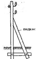
Structure Types in Use
Structures come in a wide variety of styles:
• lattice towers
• cantilevered or guyed poles and masts
• framed structures
• combinations of the above
They are available in a wide variety of materials:
• Metal
galvanized steel and aluminum rods, bars and rolled shapes fabricated plate tubes
• Concrete
spun with pretensioned or post-tensioned reinforcing cable statically cast nontensioned reinforcing steel single or multiple piece
• Wood
as grown glued laminar
• Plastics
• Composites
• Crossarms and braces
• Variations of all of the above
Depending on their style and material contents, structures vary considerably in how they respond to load. Some are rigid. Some are flexible. Those structures that can safely deflect under load and absorb energy while doing so, provide an ameliorating influence on progressive damage after the failure of the first element.
TEXT 23.Power electronics.
Power semiconductor devices are the most important functional elements in all power conversion applications. The power devices are mainly used as switches to convert power from one form to another. They are used in motor control systems, uninterrupted power supplies, high-voltage DC transmission, power supplies, induction heating, and in many other power conversion applications.
The thyristor, also called a silicon-controlled rectifier (SCR), is basically a four-layer three-junction pnpndevice. It has three terminals: anode, cathode, and gate. The device is turned on by applying a short pulse across the gate and cathode. Once the device turns on, the gate loses its control to turn off the device. The turn-off is achieved by applying a reverse voltage across the anode and cathode. There are basically two classifications of thyristors: converter grade and inverter grade. The difference between a converter-grade and an inverter- grade thyristor is the low turn-off time (on the order of a few microseconds) for the latter. The converter- grade thyristors are slow type and are used in natural commutation (or phase-controlled) applications. Inverter-grade thyristors are used in forced commutation applications such as DC-DCchoppers and DC-AC inverters. The inverter-grade thyristors are turned off by forcing the current to zero using an external commutation circuit. This requires additional commutating components, thus resulting in additional losses in the inverter.
The Gate Turn-off (GTO) thyristor is a power switching device that can be turned on by a short pulse of gate current and turned off by a reverse gate pulse. This reverse gate current amplitude is dependent on the anode current to be turned off. Hence there is no need for an external commutation circuit to turn it off. Because turn-off is provided by bypassing carriers directly to the gate circuit, its turn-off time is short, thus giving it more capability for high-frequency operation than thyristors.
Reverse-Conducting Thyristor (RCT) and Asymmetrical Silicon-Controlled Rectifier (ASCR).
Normally in inverter applications, a diode in antiparallel is connected to the thyristor for commutation/freewheeling purposes. In RCTs, the diode is integrated with a fast switching thyristor in a singlesilicon chip. Thus, the number of power devices could be reduced. This integration brings forth a substantial improvement of the static and dynamic characteristics as well as its overall circuit performance.
The RCTs are designed mainly for specific applications such as traction drives. The antiparallel diode limits the reverse voltage across the thyristor to 1 to 2 V. Also, because of the reverse recovery behavior of the diodes, the thyristor may see very high reapplied dv/dt when the diode recovers from its reverse voltage.
Power transistors are used in applications ranging from a few to several hundred kilowatts and switching frequencies up to about 10 kHz. Power transistors used in power conversion applications are generally npn type. The power transistor is turned on by supplying sufficient base current, and this base drive has to be maintained throughout its conduction period. It is turned off by removing the base drive and making the base voltage slightly negative. The saturation voltage of the device is normally 0.5 to 2.5 V and increases as the current increases. Hence, the on-state losses increase more than proportionately with current. The transistor off-state losses are much lower than the on-state losses because the leakage current of the device is of the order of a few milliamperes. Because of relatively larger switching times, the switching loss significantly increases with switching frequency. Power transistors can block only forward voltages. The reverse peak voltage rating of these devices is as low as 5 to 10 V. Power transistors do not have Pt withstand capability. In other words, they can absorb only very little energy before breakdown. Therefore, they cannot be protected by semiconductor fuses, and thus an electronic protection method has to be used.
Power MOSFETs are marketed by different manufacturers with differences in internal geometry and with different names such as MegaMOS, HEXFET, SIPMOS, and TMOS. They have unique features that make them potentially attractive for switching applications. They are essentially voltage-driven rather than current-driven devices, unlike bipolar transistors.
The gate of a MOSFET is isolated electrically from the source by a layer of silicon oxide. The gate draws only a minute leakage current on the order of nanoamperes. Hence, the gate drive circuit is simple and power loss in the gate control circuit is practically negligible. Although in steady state the gate draws virtually no current, this is not so under transient conditions. The gate-to-source and gate-to-drain capacitances have to be charged and discharged appropriately to obtain the desired switching speed, and the drive circuit must have a sufficiently low output impedance to supply the required charging and discharging currents.
The Insulated-Gate Bipolar Transistor (IGBT) has the high input impedance and high-speed characteristics of a MOSFET with the conductivity characteristic (low saturation voltage) of a bipolar transistor. The IGBT is turned on by applying a positive voltage between the gate and emitter and, as in the MOSFET, it is turned off by making the gate signal zero or slightly negative. The IGBT has a much lower voltage drop than a MOSFET of similar ratings. The structure of an IGBT is more like a thyristor and MOSFET. For a given IGBT, there is a critical value of collector current that will cause a large enough voltage drop to activate the thyristor. Hence, the device manufacturer specifies the peak allowable collector current that can flow without latch- up occurring. There is also a corresponding gate source voltage that permits this current to flow that should not be exceeded.
Like the power MOSFET, the IGBT does not exhibit the secondary breakdown phenomenon common to bipolar transistors. However, care should be taken not to exceed the maximum power dissipation and specified maximum junction temperature of the device under all conditions for guaranteed reliable operation. The on-state voltage of the IGBT is heavily dependent on the gate voltage. To obtain a low on-state voltage, a sufficiently high gate voltage must be applied.
MOS-Controlled Thyristor (MCT) is a new type of power semiconductor device that combines the capabilities of thyristor voltage and current with MOS gated turn-on and turn-off. It is a high power, high frequency, low conduction drop and a rugged device, which is more likely to be used in the future for medium and high power applications.
1. Read and translate the text.
2. Answer the following questions.
1) What is the difference between converter-grade and an inverter- grade thyristor?
2) Why canthe number of power devices in RCT be reduced?
3) How is the power transistor turned on?
4) What method is used to protect power transistors?
5) What is the structure of an IGBT similar to?
6) What is the on-state voltage of the IGBT dependent on?
3. Findthe syn on y ms.
| Negligible
| fall, decrease
|
| exceed
| different
|
| withstand
| concerning, with regards to
|
| drop
| Acceptable, suitable
|
| unlike
| get
|
| with respect to
| tiny, unimportant
|
| obtain
| survive, resist, endure
|
| attractive
| surpass, overfulfill
|
| rugged
| durable, reliable, sturdy
|
4. Complete the table below, using a dictionary.
| Verb
| Noun (idea)
| Adjective
| Adverb
|
| -
| -
| allowable
| -
|
| require
| -
| -
| -
|
| combine
| -
| -
| -
|
| -
| conductivity
| -
| -
|
| -
| capability
| -
| -
|
| -
| -
| relatively
| -
|
| | | | |
5. Write down the characteristic features of SCR, GTO,RCT, MOSFET, IGBT and MCT in a given table:
| SCR
| GTO
| RCT
| MOSFET
| IGBT
| MCT
|
|
|
|
|
|
|
|
TEXT 24. Power Quality. Harmonics in Power Systems
Electric power quality has emerged as a major area of electric power engineering. The predominant reason for this emergence is the increase in sensitivity of end-use equipment. While grounding, voltage sags, harmonics, voltage flicker, and long-term monitoring do not cover all aspects of power quality, they provide a broad - based overview that should serve to increase overall understanding of problems related to power quality.
Proper grounding of equipment is essential for safe and proper operation of sensitive electronic equipment.According to the National Electric Code it is essential to insure proper and trouble-free equipment operation, and also to insure the safety of associated personnel.
Other than poor grounding practices, voltage sags due primarily to system faults are probably the most significant of all power quality problems. Voltage sags due to short circuits are often seen at distances very remote from the fault point, thereby affecting a potentially large number of utility customers. Coupled with the wide-area impact of a fault event is the fact that there is no effective preventive for all power system faults. End-use equipment will, therefore, be exposed to short periods of reduced voltage which may or may not lead to malfunctions.
Like voltage sags, the concerns associated with flicker are also related to voltage variations. Voltage flicker, however, is tied to the likelihood of a human observer to become annoyed by the variations in the output of a lamp when the supply voltage amplitude is varying. In most cases, voltage flicker considers (at least approximately) periodic voltage fluctuations with frequencies less than about 30-35 Hz that aresmall in size. Human perception, rather than equipment malfunction, is the relevant factor when considering voltage flicker.
For many periodic waveform (either voltage or current) variations, the power of classical Fourier series theory can be applied. The terms in the Fourier series are called harmonics; relevant harmonic terms may have frequencies above or below the fundamental power system frequency. In most cases, nonfundamental frequency equipment currents produce voltages in the power delivery system at those same frequencies. This voltage distortion is present in the supply to other end-use equipment and can lead to improper operation of the equipment.
Power system harmonics are not a new topic, but the proliferation of high-power electronics used in motor drives and power controllers has necessitated increased research and development in many areas relating to harmonics. For many years, high-voltage direct current (HVDC) stations have been a major focus area for the study of power system harmonics due to their rectifier and inverter stations. Roughly two decades ago, electronic devices that could handle several kW up to several MW became commercially viable and reliable products. This technological advance in electronics led to the widespread use of numerous converter topologies, all of which represent nonlinear elements in the power system.
Even though the power semiconductor converter is largely responsible for the large-scale interest in power system harmonics, other types of equipment also present a nonlinear characteristic to the power system. In broad terms, loads that produce harmonics can be grouped into three main categories: coveringarcing loads, semiconductor converter loads, and loads with magnetic saturation of iron cores.
Arcing loads, like electric arc furnaces and florescent lamps, tend to produce harmonics across a wide range of frequencies with a generally decreasing relationship with frequency. Semiconductor loads, such as adjustable-speed motor drives, tend to produce certain harmonic patterns with relatively predictable amplitudes at known harmonics. Saturated magnetic elements, like overexcited transformers, also tend to produce certain “characteristic” harmonics. Like arcing loads, both semiconductor converters and saturated magnetics produce harmonics that generally decrease with frequency.
1. Read and translate the text.
2. Read and decide if the following statements are true (T) or false (F).
1) Proper grounding of equipment is essential for safe operation of equipment.
2) Voltage sags due to short circuits are hardly seen at distances very remote from the fault point.
3) Voltage flicker is irritating for people.
4) The power of classical Fourier series theory can be used for several periodic waveform variations.
5) Voltage distortion can lead to incorrect operation of the equipment.
6) Power system harmonics have been studied for a long time.
7) Nonlinear elements in the power system became widespread not long ago.
3. Put the following words in the correct order to form a sentence.
1) Insure, it, the, essential, to, proper, is, operation, of, equipment.
2) Voltage, customers, of, sags, affect, large, can, number, utility.
3) Power, largely, semiconductor, the, converter, responsible, is?
4) by, cannot, transistors,protected, semiconductor, fuses, power, be.
5) Semiconductor, elements, most, are, devices, power, the,important, functional.
4. Match the words from the text with their corresponding definitions.
| Voltage sag
| the power output of a generator or power plant.
|
| adjustable
| To state, tell about, or make known in advance, especially on the basis of special knowledge
|
| harmonic
| Any of a series of periodic waves whose frequencies are integral multiples of a fundamental frequency.
|
| load
| Unable to hold or contain more; full
|
| predictable
| to move or change (something) so as to be in a more effective arrangement or desired condition
|
| Saturated
| is a short duration reduction in rms voltage which can be caused by a short circuit, overload or starting of electric motors
|
| large-scale
| wide-ranging or extensive.
|
5. Write the summary of the text.
TEXT 1. Electric Power Generation: Non-Conventional Methods. Wind Power
The wind is a free, clean, and inexhaustible energy source. It has served humankind well for many centuries by propelling ships and driving wind turbines to grind grain and pump water. Denmark was the first country to use wind for generation of electricity. The Danes were using a 23-m diameter wind turbine in 1890 to generate electricity. By 1910, several hundred units with capacities of 5 to 25 kW were in operation in Denmark.
In addition to home wind-electric generation, a number of utilities around the world have built larger wind turbines to supply power to their customers. The largest wind turbine built before the late 1970s was a 1250-kW machine built on Grandpa’s Knob, near Rutland, Vermont, in 1941. This turbine, called the Smith-Putnam machine, had a tower that was 34 m high and a rotor 53 m in diameter. The rotor turned an ac synchronous generator that produced 1250 kW of electrical power at wind speeds above 13 m/s.
After World War II, we entered the era of cheap oil imported from the Middle East. Interest in wind energy died and companies making small turbines folded. The oil embargo of 1973 served as a wakeup call, and oil-importing nations around the world started looking at wind again.
The U.S. immediately started to develop utility-scale turbines. It was understood that large turbines had the potential for producing cheaper electricity than smaller turbines, so that was a reasonable decision. The government funded a number of test turbines, from the 100 kW MOD-0 to the 2500 kW MOD-2. These ran for brief periods of time, a few years at most. Once it was obvious that a particular design would never be cost competitive, the turbine was quickly salvaged.
In 1986, there were 25 wind turbine manufacturers in Denmark. The Danish market gave them a base from which they could also sell to other countries.
Prices have dropped substantially since 1973, as performance has improved. It is now commonplace for wind power plants (collections of utility-scale turbines) to be able to sell electricity for under four cents per kilowatt hour.
Total installed worldwide capacity at the start of 1999 was almost 10,000 MW.
One of the most critical features of wind generation is the variability of wind. Wind speeds vary with time of day, time of year, height above ground, and location on the earth’s surface. This makes wind generators into what might be called energy producers rather than power producers. That is, it is easier to estimate the energy production for the next month or year than it is to estimate the power that will be produced at 4:00 pm next Tuesday. Wind power is not dispatchable in the same manner as a gas turbine. A gas turbine can be scheduled to come on at a given time and to be turned off at a later time, with full power production in between. A wind turbine produces only when the wind is available. At a good site, the power output will be zero (or very small) for perhaps 10% of the time, rated for perhaps another 10% of the time, and at some intermediate value the remaining 80% of the time.
This variability means that some sort of storage is necessary for a utility to meet the demands of its customers, when wind turbines are supplying part of the energy. This is not a problem for penetrations of wind turbines less than a few percent of the utility peak demand. In small concentrations, wind turbines act like negative load. That is, an increase in wind speed is no different in its effect than a customer turning off load. The control systems on the other utility generation sense that generation is greater than load, and decrease the fuel supply to bring generation into equilibrium with load. In this case, storage is in the form of coal in the pile or natural gas in the well.
An excellent form of storage is water in a hydroelectric lake. Most hydroelectric plants are sized large enough to not be able to operate full-time at peak power. They therefore must cut back part of the time because of the lack of water. A combination hydro and wind plant can cons