
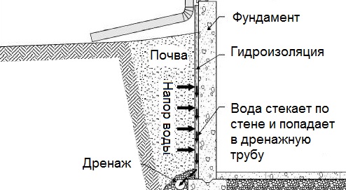
Общие условия выбора системы дренажа: Система дренажа выбирается в зависимости от характера защищаемого...
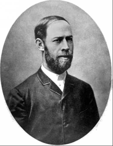
История создания датчика движения: Первый прибор для обнаружения движения был изобретен немецким физиком Генрихом Герцем...
Общие условия выбора системы дренажа: Система дренажа выбирается в зависимости от характера защищаемого...
История создания датчика движения: Первый прибор для обнаружения движения был изобретен немецким физиком Генрихом Герцем...
Топ:
Установка замедленного коксования: Чем выше температура и ниже давление, тем место разрыва углеродной цепи всё больше смещается к её концу и значительно возрастает...
История развития методов оптимизации: теорема Куна-Таккера, метод Лагранжа, роль выпуклости в оптимизации...
Определение места расположения распределительного центра: Фирма реализует продукцию на рынках сбыта и имеет постоянных поставщиков в разных регионах. Увеличение объема продаж...
Интересное:
Подходы к решению темы фильма: Существует три основных типа исторического фильма, имеющих между собой много общего...
Инженерная защита территорий, зданий и сооружений от опасных геологических процессов: Изучение оползневых явлений, оценка устойчивости склонов и проектирование противооползневых сооружений — актуальнейшие задачи, стоящие перед отечественными...
Берегоукрепление оползневых склонов: На прибрежных склонах основной причиной развития оползневых процессов является подмыв водами рек естественных склонов...
Дисциплины:
|
из
5.00
|
Заказать работу |
Содержание книги
Поиск на нашем сайте
|
|
|
|
Regardless of bit type, it must be rotated in order to drill the rock. There are three methods used to turn the bit downhole:
1. The drillstring and bit are turned by a rotary table and kelly.
2. The drillstring and bit are rotated by a “top-drive” motor.
3. Only the bit is rotated by a hydraulic mud motor in the drillstring. (The drillstring can be held still or rotated while using a mud motor, as desired.)
Rotary table and kelly. A rotary table is a gear- and chain-driven turntable mounted into the rig floor that has a large open center for the bit and drillstring. The rotary table kelly bushing is a large, metal “donut” with a 4-, 6- or 8- sided hole at its center. This bushing can accept a special piece of 4-, 6- or 8-sided pipe, called the kelly. The kelly, which is about 40 ft long, is turned by the Kelly bushing in the rotary table, just as a hex nut is turned by a wrench. The kelly is free to slide up and down in the Kelly bushing so it can be raised while a 30-ft joint of drill pipe (the topmost joint in the drillstring) is attached to its bottom. The drill pipe is then lowered into the hole until the bit touches bottom, and the kelly can be rotated. The driller starts the rotary table, and as the bit drills down, the kelly moves down, too. When the top end of the kelly is level with the bushing (at rig floor level), the kelly is broken out from the drill pipe, raised while another joint is added, and the process of drilling down is repeated. In order for the drilling mud to get into the drillstring, a rotary hose and mud swivel are attached to the top of the kelly to supply mud from the mud pumps. The swivel is a hollow device that receives mud from the stand pipe and rotary hose and passes it through a rotating seal to the kelly and into the drillstring. One disadvantage of the kelly/rotary arrangement is that while pulling pipe with the kelly disconnected, no mud can be pumped and pipe rotation is minimal.
Methods used to turn the bit (2,3)
Top drive. A top-drive unit has important advantages over a kelly/rotary drive. A top-drive unit rotates the drillstring with a large hydraulic motor mounted high in the derrick on a traveling mechanism. Top drives use 3-joint (90-ft) “stands” of drill pipe and reduce the number of connections and the time to make a trip. One key advantage — the driller can simultaneously rotate the pipe while going up or down over a 90 ft distance in the hole and circulate mud. This allows long, tight spots to be quickly and easily reamed without sticking the pipe. Due to these advantages, top drive units are being installed on most deep rigs and offshore rigs.
Mud motor. While the first two rotation methods involve turning the drill pipe in order to turn the bit, this method is different. In this case, there is a hydraulic motor (turbine or positive-displacement mud motor) mounted in the BHA near the bit. During drilling, hydraulic energy from the mud passing through the motor turns the bit. This is achieved through the use of multiple rotor/stator elements inside the motor which rotate a shaft to which the bit is attached. This offers several advantages. Mud motors can achieve much higher bit rotational speeds than can be achieved by rotating the entire drillstring. Less energy is required to turn just the bit. The hole and casing stay in better condition, as does the drillstring, when only the bit (and not the pipe) rotates. Higher bit RPM results in improved Rate of Penetration (ROP), and vibration is less of a problem. Mud motors are used extensively for directional drilling where it is essential to keep an orienting tool positioned in the desired direction.
Casing and liner
When a well is being drilled, exposed formations must be periodically covered and protected by steel pipe. This is done for several reasons — to keep the hole from caving in, to protect the formations being drilled and/or to isolate different geological zones from each other. These protective pipes are called casings and liners. Casing refers to pipe that starts at the surface or mud line and extends down into the borehole. The term liner applies to pipe whose upper end does not reach the surface or mud line but is inside and overlaps the bottom of the last casing or liner. Casing and liners are either totally or partially cemented in place.
Casing. Two, three or more casing strings may be run in a well, with the smaller pipe being run inside the larger sizes, and the smaller ones going deeper than the larger. The “surface casing” is run and cemented at a depth to protect freshwater aquifers and to avoid mud seepage into shallow sand and gravel beds; it might be set at about 2,000 ft. The next string is the “intermediate” casing. It is run and cemented when there’s a need to change the mud to a density that can’t be tolerated by the exposed formations or by the surface casing. Below the intermediate casing may be another string of casing or a liner.
Liners. It may not be necessary, economical or practical to line the entire, already-cased hole all the way to the surface just to protect the lower open hole. This is especially true as the hole nears total depth and becomes smaller. So a liner is run from the bottom of the hole, up into the casing, overlapping it by several hundred feet. Liners are held in place inside the casing by special tools called liner hangers. The practice of running a liner protects the last open hole interval, which often includes the reservoir section.
The drillstring (1)
Starting at the bottom, a basic drillstring for rotary drilling consists of the (1) bit, (2) drill collars and Bottom-Hole Assemblies (BHAs), and (3) drill pipe.
The BHA is located just above the bit and consists of drill collars combined with one or more bladed stabilizers (to keep the BHA and bit concentric), possibly a reamer (to keep the hole from becoming tapered as the bit diameter wears down) and other tools. MWD tools and mud motors are generally located low in the BHA, usually just above the bit. Sometimes, a set of “jars” is located near the top of the BHA. Jars (ясы) can free stuck pipe by giving a hammering action when they are set-off by pulling hard.
Drill collars are thick-walled, heavy joints of pipe used in the BHA to provide weight to the bit. Usually, one of the collars is made of non-magnetic metal so that a magnetic compass tool (survey tool) can be used to determine the inclination of the lower BHA and bit without interference from magnetic metals.
Each joint of drill pipe is approximately 30 ft long, and has a box (female connection) welded onto one end and a pin (male connection) welded to the other. These threaded couplings (tool joints) must be strong, reliable, rugged and safe to use. They must be easy to make up (connect) and break out (disconnect). Outer diameters for drill pipe range from 23⁄8 to 6 5⁄8 in.
The drillstring (2)
The hollow drill string provides a means for continuous circulation and for pumping drilling mud under high pressure through the bit nozzles as a jet of fluid. The blast of mud knocks rock cuttings from under the bit, gives a new rock surface for the cutters to attack and starts the drill cuttings on their trip to the surface. This transmission of hydraulic horsepower from the mud pumps to the bit is a very important function of the mud.
Coiled-tubing drilling. This method employs a continuous string of coiled tubing and a specialized, coiled-tubing drilling rig. Rather than drilling with separate joints of the traditional, large diameter, rigid drill pipe, the drillstring is smaller-diameter, flexible tubing. Unlike drill pipe which is screwed together to form the drillstring, and which must be disconnected into stands that are racked in the derrick during trips, the tubing comes rolled on a reel that unwinds as drilling progresses and is subsequently rewound onto its spool during trips. The coiled-tubing method greatly facilitates lowering and retrieving the drilling assembly.
Traditionally, coiled-tubing rigs have been used for workover (КРС –капитальный ремонт скважин) and completion operations where mobility and compact size were important. With the development of downhole mud motors which do not require the use of a rotating drillstring to turn the bit, coiled-tubing units are now functioning as true drilling rigs.
Drilling crew
The typical drilling rig crew consists of a driller, two or three floormen or «roughnecks», a derrickman and perhaps a motorman.The drilling operation is supervised by a drilling supervisor, more often known as a drilling foreman or tool, pusher augmented by a drilling engineer, a wellsite geologist, a mud engineer and a mud logger. The floormen do the hard work on the rig floor consists of mainly of making and breaking connections and adding or removing joints of drillpipe, while the derrickman assists the operation on the «monkey board» 60, 90 or 120 feet up in the derrick. The driller controls all the rig functions and handles the brakes from his console.
A single drilling crew normally works an 8 - hour tour (pronounced «tower») each day. However in remote or offshore locations a crew may work a 12 - hour tour. When running casing a special casing crew is called in, or a drilling crew will work overtime to assists the next tower crew in the operation. Typically, the toolpusher and the drilling crew will be employees of a drilling contractor, whereas the drilling engineer and well site geologist are employees of producing company or consultants.
Well drilling is a job that usually goes on twenty four hours a day, seven days a week, including most holidays. As a result the contractor must hire at least three or sometimes four complete crews. The people who work on rigs usually work in shifts. If the land rig is located near the city the crew can drive to and from work every day. But in remote areas, where distances to the rig are often measured in thousands of kilometers a crew cannot economically travel back and forth every day, so, the contractor provides comfortable, temporary living condition.
LITERATURE USED:
1. F.Jahn, M.Cook & M. Graham // Hydrocarbon Exploration and Production.-
Elsevier, UK, 2003.
2. Drilling fluids Engineering Manual by Magcobar Division // Oilfield Products
Group - Dresser Industries (author), 1997.
3. http://www.spe.org
4. http//www.world_oil.com
|
|
|
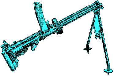
История развития пистолетов-пулеметов: Предпосылкой для возникновения пистолетов-пулеметов послужила давняя тенденция тяготения винтовок...
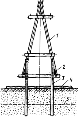
Особенности сооружения опор в сложных условиях: Сооружение ВЛ в районах с суровыми климатическими и тяжелыми геологическими условиями...
Состав сооружений: решетки и песколовки: Решетки – это первое устройство в схеме очистных сооружений. Они представляют...
Организация стока поверхностных вод: Наибольшее количество влаги на земном шаре испаряется с поверхности морей и океанов (88‰)...
© cyberpedia.su 2017-2026 - Не является автором материалов. Исключительное право сохранено за автором текста.
Если вы не хотите, чтобы данный материал был у нас на сайте, перейдите по ссылке: Нарушение авторских прав. Мы поможем в написании вашей работы!

