From the results, it can be seen that the maximum value of L is reached at a
12 MPa pressure in the combustion chamber and a 0.2 MPa pressure after the turbine, in which case L is equal to 22. Since real SP does not contain 73% of HMX, and, ordinarily, HMX is added up to 50% of total oxidizer [4], then the dependence of the specific impulse on the flow rate ratio L (Fig. 3) was calculated for the compositions: 70% OX + 30% SKI-NL (Composition 1) and 68% OX + 32% SKI-NL (Composition 2), where OX is an oxidizing agent, 50% of which is HMX and 50% ammonium perchlorate (AP) [1]. It is worth noting that the L values obtained for AP + SKI-NL do not practically differ from the L values obtained for HMX + SKI-NL. Thus, the maximum L value for Composition 1 and Composition 2 will be the same as for HMX-based SP (Fig. 2).
Based on the graphin Figure 3, the maximum specific thermodynamic impulse for the RTE is 1409 s. Whereas the LPRE has it equal to 300 ÷ 350 s, the SPRE has it equal to 250 ÷ 300 s and RRE˗ 600 ÷ 1000 s [4]. The RTE solid propellant has good performance characteristics (like those of solid propellants), while it is possible to regulate the thrust by switching on several GGs (Fig. 1). In contrast to the RRE, the proposed engine does not need a booster unit (starting engine), which means that the mass characteristics of the RTE are much higher than those of the combined RRE.

Figure 3 - RTE specific thermodynamic impulse.
Conclusion
1. A solid fuel rocket turbine engine has a high thermodynamic specific impulse - about 1400 s, which is 4–6 times more than that of liquid and solid propellant rocket engines and 1.5–2 times more than that of ramjet rocket engines.
2. Rocket turbine engine solid propellant has good performance like solid rocket propellant in the SPRE.
3. The engine thrust can be regulated both by means of an adjustable nozzle and by switching on additional gas generators. At the same time, the rocket-turbine engine still loses in the regulation to the liquid-propellant engine, because thrust control is much more complex, and there is no possibility of multiple engine restart. Therefore, it makes sense to consider using granular solid fuels instead of conventional ones. Theoretically, this will make it possible to turn off the rocket turbine engine many times and expand the thrust control range to 10.
Reference list
1. Concept and Performance Study of Turbocharged Solid Propellant Ramjet, Acta Astronautica / J. Li, K. Liu, Y. Liu [et al.]. – Text : electronic // ResearchGate : [site]. – URL:https://www.researchgate.net/publication/324070037_Concept_and_performance_study_of_turbocharged_solid_propellant_ramjet (date accessed: 21.02.2021)
2. Bazhukov, A. S. Gazoturbinnye i raketoturbinnye dvigateli na tverdom toplive dlya bespilotnyh letatel'nyh apparatov, rabotayushchih v ekstremal'nyh usloviyah / A. S. Bazhukov, P. A. Mitrovich, V. I. Malinin // Messenger of Perm National Research Polytechnical University. Aerokosmicheskaya tekhnika. 2018. № 55. P. 70–80.
3. Rivkin, S. L. Termodinamicheskie svojstva gazov : spravochnik / S. L. Rivkin. – 4-e izd., pererab. – Moscow : Energoatomizdat, 1987. – 288 s. : il.
4. Teoreticheskie osnovy analiza i sinteza kombinirovannyh raketnyh dvigatelej na tverdyh i pastoobraznyh toplivah / B. V. Obnosov, V. A. Sorokin, L. S. YAnovskij [and oth.]. – Moscow : Dashkov i K, 2012. – 244 p.
| Mikhail Sitnikov
| Михаил Ситников
|
| Perm National Research Polytechnic University
| Пермский Национальный Исследовательский Политехнический Университет
|
| Investigation of the contact fracture of ball bearing samples surfaces by vibrometry technique
| Термодинамический удельный импульс твердотопливного ракетного турбинного двигателя
|
| Abstract: this article shows specific features of gas turbine engine, which is really important for everyday life. Author gives photos of damage of bearing parts of gas turbine engine. Also you can find spreadsheets, frameworks and necessary calculations in this article.
| Аннотация: В этой статье показаны особенности газотурбинного двигателя, что очень важно для повседневной жизни. Автор представляет фотографии повреждений несущих частей газотурбинного двигателя. Также вы можете найти таблицы, схемы и необходимые вычисления в этой статье.
|
Introduction
The bearing assembly is one of the most critical and vulnerable components of the GTE (gas turbine engine). Any GTE bearing failure entails the failure of the entire GTE. The increased velocities of the bearing operation in the GTE lead to significant dynamic loads, which form an inhomogeneous vibration field. The created vibration field, being transformed to rotational frequencies, structures possible zones of physical fracture processes that affect the bearing life. The need of this work is caused by the lack of experimental data on the calculation of the durability of aircraft rolling bearings with a long life. And the correct prediction of the bearing life will allow to carry out engine maintenance in time to avoid bearing failure.
The main damage type of the GTE bearing parts is fatigue spalling on the contact surfaces of the rolling elements and treadmills of the rings, an example is shown in Figure 1.
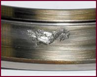
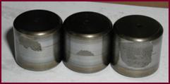
Figure 1 - Fatigue spalling on the contact surfaces of the rollers and treadmills of the rings
Contact fatigue of ball bearing steel occurs as a result of the growth of existing microcracks on the operating surfaces [1]. During operation short-term shock pulses may occur on rolling surfaces in the zone of contact with the defect which excite additional vibration in a wide frequency band [2], [3]. In the most general case the assessment of the technical condition and the search for rolling bearing defects can be performed using the RMS vibration acceleration value, the vibration signal spectrum, the peak / background ratio of the vibration signal, and the signal envelope spectrum.
Experiment
In the process of contact endurance tests the samples are subjected to cyclic loading under conditions of increased velocities and loads. One of the main tasks during such tests is to register the beginning of surface fracture of samples — the appearance of pitting on the rolling surface. The diagnostic method should have a high sensitivity to incipient defects and a high signal response rate for the timely completion of the test. Considered methods of vibration diagnostics show that the analysis of the envelope spectrum of the vibration acceleration signal meets these criteria and is a priority method for fracture beginning diagnosing. Figure 2 shows the envelope spectrum of the vibration acceleration signal at the moment when the unit enters the nominal operation mode (a) and before the test is completed (b).

(a)
(b)
Figure 2 - The envelope spectrum of the vibration acceleration signal in the frequency range Δ f = 4471-5634 Hz at the beginning of the test (a) and before the end of the test (b)
At the initial moment of the test the spectrum of the envelope of the vibration acceleration signal has no amplitudes at the characteristic frequencies of the defect of the samples and their harmonics; it is observed only the noise component of vibration. Before the end of the test when the defect reaches a sufficiently large size the amplitudes at the frequency of the sample defect and its harmonics are allocated on the envelope spectrum, as shown in Figure 1 (b). The vibration parameters at the initial moment and at the end of the test are shown in Tables 1 and 2.
Table 1 - vibration parameters of the signal from the sensor at the initial moment of the test
| Load
| Rotation velocity n, rpm
| rms, m/s2
|  , Hz , Hz
| A max m / s2
| A1 BPF,m/s2
| A2 BPF, m/s2
| A3 BPF, m/s2
| A4 BPF, m/s2
| A5 BPF, m/s2
|
|
| Frequency range 5633–7096 Hz
|

| 10 044
| 17.40
| 754
| 111.5
| 0.12
| 0.03
| –
| –
| –
|
|
| Frequency range 7096–8941 Hz
|
|
| 10 044
| 17.40
| 754
| 111.5
| 0.13
| 0.06
| 0.07
| –
| –
|
|
| Frequency range 8941–11265 Hz
|
|
| 10 044
| 17.40
| 754
| 111.5
| 0.08
| 0.05
| –
| –
| –
|
“–” — no informative component was detected.
Table 2 - vibration parameters of the sensor signal before the end of the test
| Load
| Rotation velocity n, rpm
| rms, m/s2
|  , Hz , Hz
| A max, m / s2
| A1 BPF,m/s2
| A2 BPF,m/s2
| A3 BPF,m/s2
| A4 BPF,m/s2
| A5 BPF,m/s2
|
|
| Frequency range 5633–7096 Hz
|
|
| 10 044
| 40.52
| 754
| 159.4
| 4.37
| 0.77
| 0.82
| 0.35
| 0.32
|
|
| Frequency range 7096–8941 Hz
|
|
| 10 044
| 40.52
| 754
| 159.4
| 8.7
| 4.04
| 1.69
| 0.48
| 0.27
|
|
| Frequency range 8941–11265 Hz
|
|
| 10 044
| 40.52
| 754
| 159.4
| 5.05
| 2.30
| 2.71
| 1.17
| 0.28
|
The magnitude of the amplitudes, as well as the presence of higher and additional side harmonics, can indicate the level of damage. Images of the ball sample surface before and after the test are shown in Figure 3.


(a) (b)
Figure 3 - Sample surface before the test (a) and after the test (b)
On the surface of the ball sample after the test, there are multiple cavity defects and material carry-overs from the surface.
Conclusion
The determination of the contact fracture beginning on the test samples by the analysis of signal envelope vibration acceleration shows good results and makes possible to unambiguously determine the appearance and trace the development of the defect while testing the contact endurance of bearing steel samples. Further experimental studies are required to determine the dependency of the values of vibration diagnostic parameters on the level of surface damage.
Reference list
1. Трубин, Г. К. Контактная усталость материалов для зубчатых колес / Г. К. Трубин. – Москва : Машгиз, 1962.– 404 с.
2. Барков, А. В. Мониторинг и диагностика роторных машин по вибрации : учебное пособие / А. В Барков, Н. А. Баркова, А. Ю. Азовцев. – Санкт-Петербург : Севзапучцентр, 2013. – 158 с. : ил., табл. – ISBN 978-5-91498-034-1.
3. Ширман, А. Р. Практическая вибродиагностика и мониторинг состояния механического оборудования / А. Р. Ширман, А. Б. Соловьев. – Москва : [б. и.], 1996. – 276 с.
| Anton Naborshchikov
| Антон Наборщиков
|
| Perm National Research Polytechnic University
| Пермский Национальный Исследовательский Политехнический Университет
|
| On the reliability of a self-routing analog-to-digital converter based on a neural network
| О надежности самонаправляющего аналого-цифрового преобразователя на основе нейронной сети
|
| Abstract: the structure of an analog-to-digital converter (ADC) based on a neural network (NN) is given and an approach is proposed that allows identifying and adapting to failures of both the hardware part of the ADC and to metrological failures.
| Аннотация: представлена структура аналого-цифрового преобразователя (ADC) на основе нейронной сети (NN) и предложен подход, который позволяет выявлять и адаптировать к сбоям как аппаратной части ADC, так и к метрологическим сбоям.
|
Keywords: analog-to-digital converter, neural network, fault tolerance, self-test system.
Introduction
The development of modern digital technologies for automatic control of various processes has always been associated with solving the problems of obtaining information about the controlled object (CO). The CO parameters are measured by sensors and processed by analog-to-digital converters (ADC). The ADC generates a digital code, which is transmitted to the microprocessor of the control system (CS). If we consider complex CO (robotic arm, quadcopter navigation, aircraft engines or other devices) in order to control them, it is necessary to simultaneously measure a large number of signals. Then the need arises to separate the ADC into a separate unit. At the same time, the corresponding requirements, such as the speed of measurement, the accuracy of the data obtained, and the reliability of the entire system, are placed on the ADC [1].
The reliability of the system comes to the fore, as the increasing complexity requires the confidence of the developer in the adequacy of the initial data throughout the entire life cycle. This requires the system stability in relation to changing operating conditions (external environment, the characteristics of the hardware of the equipment, the voltage in the power supply system of the equipment). All changes that will occur in the life cycle of the equipment, cannot be taken into account at the system design stage. A reliable system must adapt to changes while retaining the ability to provide reliable data.
For example, an aircraft gas turbine engine (GTE) has a number of standard sensors: rotor speed; air / gas pressure / temperature (at the engine inlet, in the path); mass fuel consumption sensor; angles of inclination of various parts of the engine (for example, the angle of inclination of the inlet guide vanes). Thus, there are at least ten standard sensors, but in practice their number can reach more than 30.
To increase the GTE reliability, methods of duplicating the channels of sensor-regulator communication are used, which makes it possible to identify a failure, but does not allow identifying the failed channel. Recently it has become popular to introduce a majority system, where a simplified model of the engine is used as the third channel (works of V.G. Avgustinovich, T.A. Kuznetsova, F.D. Golberg, O.S. Gurevich and others). In this case, one ADC can convert the signal of one or several sensors, located either on one of the communication lines, or on two communication channels simultaneously.
Thus, the ADC under consideration must be able to identify failures and adapt to changing operating conditions.