The HF (High Frequency) communication system provides amplitude modulated or single sideband long range voice communication between aircraft to aircraft and aircraft to ground.
The frequency range allocated for commercial aviation HF communications is 2 to 30 MHz, with 1 kHz spacing making a total of 28,000 channels.
A typical HF system consists of a transceiver, control panel, aerial and aerial coupler.
The HF Transceiver
A Single Side Band (SSB) transceiver is capable of transmitting 400 watts PEP output in SSB and 125 watts carrier in AM. The transmitting and receiving range is between 2 to 30 MHz.
The receiver is normally ON unless a keying circuit is completed.
Mic audio is completed through two audio amplifiers, one of which supplies sidetone audio to the interphone system after a push to talk circuit is completed. A balanced modulator then combines the audio with a 500 kHz signal from the RF oscillator producing an upper and lower sideband output, one on each side of 500 kHz.
The sidebands are amplified and fed through one of two mechanical filters. The selection of filters is controlled by the mode selector switch on the control panel. One filter passes only the upper sideband and the other only the lower sideband. When the transceiver is operated in the AM mode, the upper sideband is passed and a 500 kHz carrier is re-inserted at the filter output. The output is then amplified and heterodyned as necessary to obtain the final transmitting frequency. A driver and power amplifier then supply the signal to the aerial.
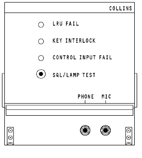
Fig. 5.1. TYPICAL HF COMMUNICATION TRANSCEIVER
A received signal is amplified and heterodyned as necessary to produce a 500 kHz IF. The 500 kHz IF is then fed to both SSB and AM IF amplifiers. In the SSB mode, the 500 kHz IF is fed to one of two mechanical filters. Each filter has a bandwidth of 3 kHz. One filter passes only the upper sideband and the other filter passes only the lower sideband depending on which mode is selected at the control panel. The filter output is then amplified and fed to a product detector where the audio signal is recovered.
In the AM mode, the 500 kHz IF is fed through a mechanical filter with a 6 kHz bandwidth to obtain both sidebands. Filter output is then amplified and fed to an AM detector which recovers the audio signals. Amplified signals are then coupled to the audio circuits of the interphone system.
HF Control Panel
The HF control panel can select any one of 28,000 channels spaced 1 kHz apart in the 2 to 30 MHz range. The mode selector switch turns the system OFF, selects upper sideband (USB), lower sideband (LSB) and amplitude modulation (AM) modes.
The RF SENS knob is a linear potentiometer which provides a manual receiver gain control. The potentiometer is connected to the receiver squelch circuit.

Fig. 5.2. HF CONTROL PANEL
HF Aerial
The purpose of the aerial is to radiate the modulated RF energy and to receive the incoming signals. Depending on the type of installation the HF aerial may be a notch or a wire aerial.
| AIRCRAFT FIN

Fig. 5.3. HF AERIALS
|
The wire aerials have a tension take up assembly which adjusts the length of aerial to maintain proper wire tension. The aerial wire is attached to the chuck body at the forward end of the assembly. The inner barrel is attached to the end of the spring and is free to move along the plunger to adjust the aerial length as required to maintain proper tension in the aerial wire. The spring is preloaded to the required tension during installation.
| 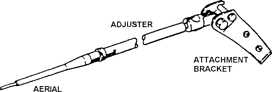
Fig. 5.4. HF AERIAL TENSION ASSEMBLY
|
The assembly will maintain the correct tension as long as the aerial wire is intact. If the aerial breaks or comes loose at the aerial mast, the tension take- up assembly unhooks from the swivel and the aerial falls away from the aircraft. Notch or Cavity aerials are used in high speed aircraft. The aerial is formed by providing a recess or notch in a suitable part of the aircraft skin and tuning the inductance of the notch to resonance at the required operating frequency. The dimensions of the notch are arranged to give an inductance of about 1 microHenry and best results are obtained if the shape of the notch is approximately square, or if rectangular, with an aspect ratio not greater than 2 to 1.
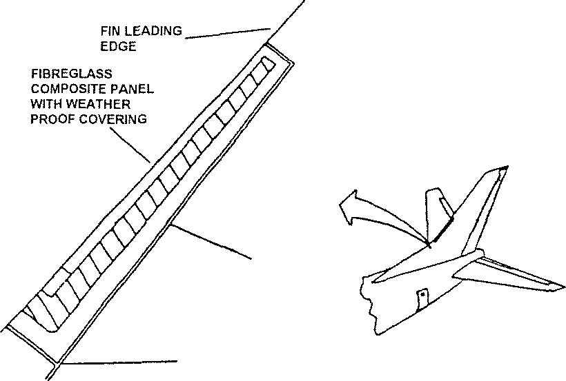
Fig. 5.5. NOTCH AERIAL
The aerial dielectric portion is constructed of aluminium honeycomb. The aerial is sandwiched and bonded between laminated fibreglass forming the leading edge of the aircraft structure.
The aerial conductor is an aluminium strip attached to the fibreglass leading edge. The lower end of the conductor is welded to an aluminium tube that is pressed flat at the opposite end. A nut plate attached to the flat surface provides the circuit attaching point for the aerial coupler. The upper end of the aerial conductor is attached to the aircraft structure and a transmission connection is provided at the attachment point.
The aerial conductor, which is located at a low impedance point in the circuit, acts as a type of inductive coupling so that the airframe operates as an aerial.
HF Aerial Coupler
An aerial system is most efficient when it is tuned to match the transmitter output. If the transmitter output impedance is 50 ohms then the aerial impedance should appear to be 50 ohms. This ensures that maximum power will be delivered to the aerial and radiated as useful power.
When the transmitter frequency has a quarter wavelength which is the same as the aerial, the aerial is considered to have an impedance of approximately 50 ohms.
However, where an aerial of a fixed length is used its impedance varies with changes in frequency.
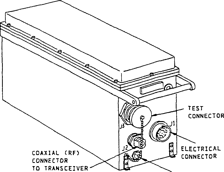
The aerial coupler automatically matches the impedance of the aerial to the characteristic impedance of the transmission line to maintain a VSWR within1.3:1 over a frequency range of 2 to 30 MHz. The coupler has the effect of electrically lengthening the aerial for lower frequencies and shortening it for the higher frequencies.
PRESSURE NOZZLE
Fig. 5.6. HF ANTENNA COUPLER
Three operations are required to match the aerial to the transmitter; sensing, control and tuning. All three occur simultaneously in the coupler. After RF power is applied to the coupler, the discriminator samples the coupler aerial input and develops dc voltages. These voltages are proportional to the following:
The reactive component (phasing error).
The 50 ohm impedance component (loading error).
The forward power level.
The reflected power level.
The two error signals indicate the degree of aerial mismatch to the servo control circuits so that commands can be made for corrective tuning action. The forward and reflected power levels are used by the control circuits to determine the tuning sequence start and completion.
A complete tuning sequence consists of four basic steps. These steps are:
1. Home.
2. Standby.
3. Tune.
4. Operate.
The steps are controlled by a sequence counter which can only advance to a new position if the conditions of the existing step or step is/are satisfied.
Home. When power is first applied or when a new frequency is selected on the control panel, a ground is switched to the coupler. The coupler sets a sequence counter to run the elements to the home position. In this position (home), the series capacitor, shunt capacitor and shunt coil are set to provide minimum attenuation. When all elements reach their home position a pulse is sent to the sequence counter to advance it to the standby position.
Standby. In the standby position, the coupler is set up to receive and the coupler is ready to start a tune cycle when it receives a key line ground. When the coupler receives the key line ground return, the sequence counter advances the system to the tune position.
Tune. Tuning is performed in three segments - A, B and C.
Segment A. In segment A, the series capacitor is servo tuned to a zero- phasing error position. At some frequencies the series capacitor alone cannot produce zero phasing. In such a case either the shunt capacitor or the shunt coil will be inserted and positioned due to band information commands so a series capacitor can produce a zero phasing error. The sequence counter then advances to segment B.
Segment B. Segment B determines whether or not the shunt coil is needed for tuning. If, after segment A, the system impedance is less than 50 ohms (negative loading) the shunt coil will not be able to resolve the loading to 50 ohms. In this case, the coupler will advance to segment C. This is typical of frequencies within the 2 to 10 MHz range. If the loading error was positive after segment A, the shunt coil will be switched on the line and servo-tuned to obtain negative loading. The phasing error will be kept at zero during segment B by the series capacitor.
When the phasing error is zero and the loading error is negative, the sequence counter advances to segment C.
Segment C. During segment C, either the shunt capacitor or the shunt coil (as selected in segments A and B) is servo-tuned to produce zero loading error. The series capacitor is fine tuned to retain a zero phasing error. At this point, the sequence counter advances to the Operate position.
Operate. On reaching the Operate sequence, the tune power and key lines unlatch and the coupler is ready to transmit and receive. If a new frequency is selected, the sequence counter advances to the home step, and the complete tuning sequence is repeated.
During a complete tuning cycle, which normally lasts 2 to 4 seconds, a 1 kHz tone is heard in the headset and the coupler locks the key line.
Where two HF communication systems are fitted to an aircraft, when a PTT switch is operated the selected transceiver and coupler are keyed. A disable signal is sent to the other aerial coupler to isolate it. This is normally achieved by breaking the PTT line of the unused transceiver and coupler.
Lightning Arrester
The lightning arrester protects the HF communication equipment by conducting lightning along a preferred path to the aircraft structure. A series capacitor with a parallel bleed resistor and a protective spark gap are installed in a pressurised chamber. The bleed resistor provides a dc path for precipitation generated static currents.
| 
ARRESTER
Fig. 5.7. LIGHTNING ARRESTER
|