Second end of the pipeline is routed into tank top (plane TT) so that the pipeline sidesteps the pump and its base along the y-axis.
To route the rest of the pipeline, move cursor near the end of the pipe and press J (connects automatically pipes), to accept the connection, press Yes. The direction is according to existing pipe segment along the z-axis so press Z to set the z-coordinate of the next system point. Let z = TT+1000 and press OK to accept the coordinate and Spacebar to accept the point.
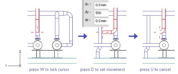
Шаг 6: Direction of Next Segment
Now you have to define the direction for the next segment. First you have lock cursor to the end of the pipe, move cursor near the pipe end and press W.
Press D to define relative coordinates from the pipe-end and let dy = 500 (enough to have an elbow), dx = 0 and dz = 0. Press Spacebar to accept the point.
Press U to cancel the previous segment, elbow remains. Now the direction of pipe segment is locked parallel to y-axis. The end of the segment is evaluated from the corner of pump base.
Шаг 7: Next System Point
To release the movement of cursor, press F5 and move cursor near the corner of pump base. Press E (nearest vertex) to lock cursor to the corner of pump base.

Press D to define the relative movement and let dy = 200, press OK to accept the coordinate and Spacebar to accept the point.

Замечание:
| Dy is evaluated from the corner of pump base. X- and z-coordinates are same as the ones at the end of the elbow. Pressing F5 didn‟t affect to those values, it just released the movement of cursor.
|
Шаг 8: End of Pipeline
Move cursor near the last point and press W to lock to the end of the pipe (nearest pipe geometry point). Press Z to set z-coordinate of the endpoint and let z = TT (tank top plane). Press Spacebar to accept the point and Enter to stop routing. Press Yes to accept the pipe.

Isometric Drawing
In this exercise you are going to create an Isometric Drawing of one pipeline at a time. First step is to create an Isometric Group of the pipeline because isometric drawing is generated via isometric group.
Although using one pipeline in an Isometric Group is a common method when creating Isometric Drawings, the other method is to create Isometric Group of several piping objects selected from several systems.
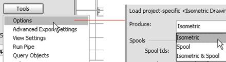
Changing Options
Use command Documents > Piping Isometrics and change the settings using command Tools > Options in Piping Isometrics panel to create Isometric Drawing without spools. Select Isometric in Produce: list and press OK.
Select the System
Because you use just one pipeline included in a certain system, the option Several Systems must be unchecked in Piping Isometrics panel.
Next you have to select the system you are working with. The list of system popups automatically (click Select button if it doesn‟t) so select the system according the area you are working with. In this example the system AA_Water is used.

Create an Isometric Group
After selecting the system, a view of Unassigned objects appears to show the pipelines which are not used in an Isometric Group, see picture below. A pipeline can be a member of one isometric group only. To select one of those pipelines for the isometric group, click Groups > Create Pipeline Isometrics.

A list of pipelines in that system appears. Take a look at of status of pipelines, all of them should be checked out by you (you have the rights to modify them) because you have routed them recently without checking in. Select one of those pipelines in the list and notice that a view named IsoView appears to indicate the selected pipeline. Press OK to create the Isometric Group of the selected pipeline.

Create an Isometric Drawing
After creating the isometric group of pipeline, create an Isometric Drawing using command Drawings > Create/Update Isometric Drawings in Piping Isometrics panel.
Select the only drawing / group from the list and check the options Annotate and Export. Annotate option add labels, symbols, dimensions etc…according to settings for automatic annotation in Pipe. Export creates an additional.pdf,.dwg.dxf etc… according to Drawing Export settings in Pipe.

Run Pipe
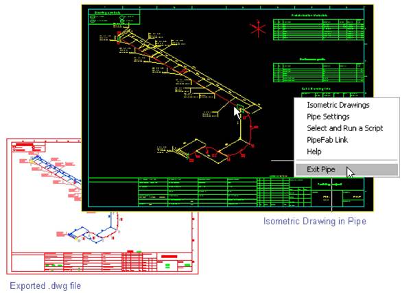
After creating the Isometric Drawing using automatic annotation, run Cadmatic Pipe to browse, edit, export, plot… the drawing(s). Select command Tools > Run Pipe in Piping Isometrics panel.

In Pipe, use command Isometric Drawings to activate browser of isometric drawings. Select folder All Drawings and status Under Work to browse the only isometric drawing in your workspace. Start viewer to browse the drawing (right-click the name of the drawing and select Browse) and right-click to get back to Isometric Drawings panel or to exit Pipe.
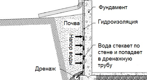
Границы области
проектирования
При первом запуске модели вы должны определить границы для области проектирования. Конструктор имеет право создавать и редактировать объекты только в пределах области проектирования. Максимальные размеры вида (окно, в котором можно работать) ограничиваются областью проектирования.
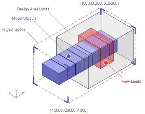
Project Space (Пространство проекта)
Это пространство, которое охватывает все области в данном проекте. Администратор должен создать одно большое пространство, необходимое для реализации проекта. Часто конструктор начинает моделирование, используя это пространство в качестве границ области проектирования. В данном случае конструктор может создавать, редактировать и видеть все объекты в проекте.