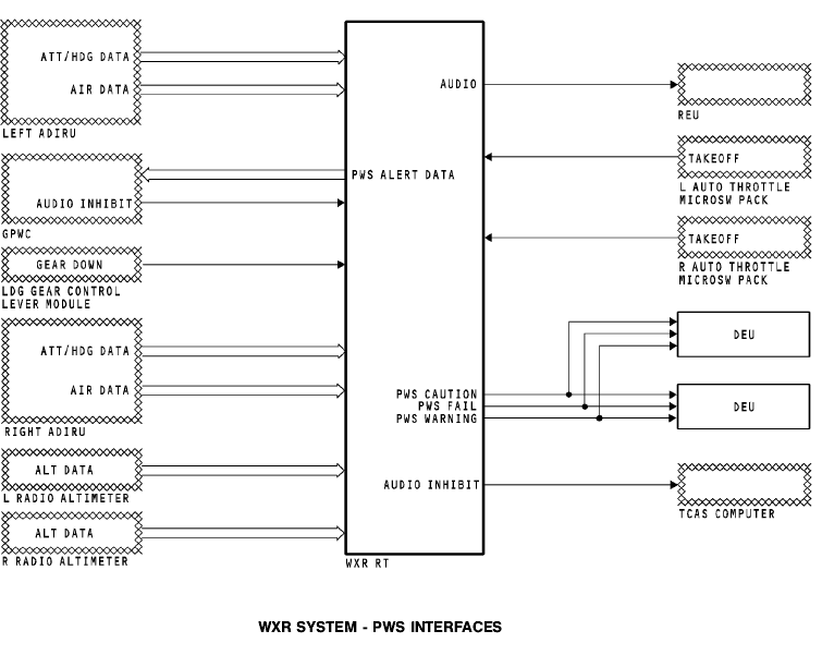
The air data inertial reference system (ADIRS) sends this data to PWS:
· Attitude Data
· Heading data
· Air data.
Ground Proximity Warning Computer
PWS sends windshear alert data to the ground proximity warning computer (GPWC) on the ARINC 708A hazard bus. The GPWC uses this data to prioritizes alerts. If there is a higher priority alert, the GPWC sends an inhibit discrete to the WXR. This discrete inhibits the PWS alert output.
Landing Gear Control Lever Module
The landing gear control lever module sends an analog discrete to PWS. PWS uses this discrete in its takeoff/ approach alert logic.
Radio Altimeter
The radio altimeter (RA) provides radio altitude data to PWS.
PWS uses radio altitude data to do these functions:
· Turn PWS on and off
· Enable/disable display and alert functions.
Remote Electronic Unit
The WXR sends the PWS aural alerts to the remote electronic unit (REU).
Autothrottle Microswitch Pack
The left and right autothrottle microswitch packs send a discrete to the PWS. The PWS uses this discrete to determine the throttle lever position for the automatic turn on.
Display Electronic Unit
The WXR sends the following discretes to the display electronic units:
· PWS warning
· PWS caution
· PWS fail.
Traffic Alert and Collision Avoidance System
WXR sends an inhibit discrete to the traffic alert and collision avoidance system (TCAS) computer when there is a PWS alert.
This discrete does these functions:
· Changes resolution advisories (RAs) to traffic advisories (TAs)
· Inhibits all TCAS audio alerts.
WXR SYSTEM - ANTENNA CONTROL INTERFACE
Antenna Tilt
The WXR panel supplies antenna tilt control signals to the WXR R/T.
Attitude Sources
The WXR R/T uses ADIRU attitude data to stabilize the antenna. The left ADIRU signals connect to the on-side attitude input of the WXR R/T. The right ADIRU signals connect to the off-side attitude input of the WXR R/T.
Attitude Source Select Discrete
Use the IRS select switch to choose the ADIRU source to the WXR R/T. Set the switch to NORMAL or BOTH ON L to use the left ADIRU input. Set the switch to BOTH ON R to use the right ADIRU input.
WXR R/T Antenna Control
The WXR R/T sends signals to the WXR antenna assembly to control it and make it stable.
Antenna Position Monitoring
The WXR antenna sends antenna position data to the WXR R/T for scan and elevation feedback.

WXR SYSTEM - CONTROL PANEL
General
The weather radar (WXR) control panel has these functions:
· Mode selection
· Tilt control
· Gain control.
Mode Selector
The captain and first officer can show separate weather radar displays. The control panel has these mode switches:
· TEST - starts a self-test of the R/T and shows the test results on the NDs
· WX - R/T shows the weather data on the NDs
· WX/T - R/T shows weather and turbulence data on the NDs.
The turbulence range is up to a maximum of 40 nautical miles (NM). If a range more than 40 NM is set on the EFIS control panel, the NDs show weather data only.
· MAP - R/T shows ground and terrain features on the NDs
· IDNT - starts ground clutter suppression
· TFR - push the left transfer switch to transfer the right side mode, tilt, and gain to the left side display.
Tilt Control
The tilt control adjusts the antenna tilt angle from +15 degrees to -15 degrees.
Gain Control
The gain controls adjust the gain for the WXR R/T signal returns. The switches have 10 detented positions. Turn the switch full clockwise for the CAL position. In the CAL position, the gain is set to a calibrated level by the R/T.
UCAL Annunciator
The UCAL annunciators show when the GAIN controls are in the uncalibrated position.