
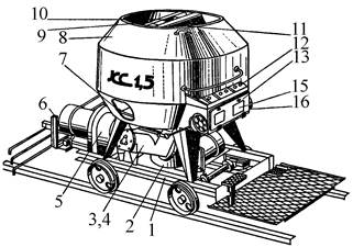
Кормораздатчик мобильный электрифицированный: схема и процесс работы устройства...
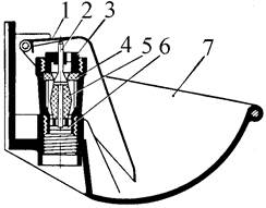
Индивидуальные и групповые автопоилки: для животных. Схемы и конструкции...
Кормораздатчик мобильный электрифицированный: схема и процесс работы устройства...
Индивидуальные и групповые автопоилки: для животных. Схемы и конструкции...
Топ:
Техника безопасности при работе на пароконвектомате: К обслуживанию пароконвектомата допускаются лица, прошедшие технический минимум по эксплуатации оборудования...
Проблема типологии научных революций: Глобальные научные революции и типы научной рациональности...
Интересное:
Мероприятия для защиты от морозного пучения грунтов: Инженерная защита от морозного (криогенного) пучения грунтов необходима для легких малоэтажных зданий и других сооружений...
Берегоукрепление оползневых склонов: На прибрежных склонах основной причиной развития оползневых процессов является подмыв водами рек естественных склонов...
Средства для ингаляционного наркоза: Наркоз наступает в результате вдыхания (ингаляции) средств, которое осуществляют или с помощью маски...
Дисциплины:
|
из
5.00
|
Заказать работу |
|
|
|
|
Lecture 1
Some details of the physics and thermodynamics.
Boyle's Law – Mariotte
At constant temperature, the specific volumes of gas are inversely proportional pressures. Specific gas volume is the volume of one kilogram of:
n = V / G, м3/кг
where V - the gas volume in m3
G - by weight of volume, in kg
According to the law of Boyle - Mariotte:
 =
=  (1)
(1)
where p1 p2 - pressure in kg / m2.
Law Gay – Lussac
At constant pressure, when the gas temperature at 10C, respectively, its volume is changed to 1/273 of the original volume.
According to Gay-Lussac's Law, the initial specific volume of gas n0 when the temperature changes at the t10 t20 respectively will be equal
n1 = n0 +  n0 t1,
n2 = n0 + n0 t2,
Dividing the first expression by the second, we get
 =
=  =
=  =
=  (2)
(2)
where Т0 = 273 + t0 It is the absolute temperature.
Surround (specific) weight g gas is the weight of one cubic meter of it:
g = G/V, kg / m3
g = 1/ v, kg / m3 (3)
From the expressions (2) and (3) have:
 ;
;
Consequently, the specific amount of gas is directly proportional to its absolute temperature and inversely proportional to volumetric weight them.
United -Mariotta Boyle and Gay - Lussac.
When you change the pressure and temperature of gas its specific volumes vary in direct proportion to the absolute temperatures and pressures inversely.
 = *
= *  , (4)
, (4)
From (4) we have:
 =
=  = const = R (5)
The value of R is called the "gas constant" and is a value characteristic of the given gas.
From (5) we obtain the main characteristic equation for gas:
p v =RT кг м/кг.
At the same pressure, p1 , changing the temperature of Т1 before Т2 will have:
p1 v1 =RT1 и p2 v2 =RT2
from whence p1 (v2 - v1)=R(T1 - T2 ) if T1 - T2 =10, то p1 (v2 - v1)=R. (7)
Consequently, there is the gas constant value 1kg expansion work of gas at constant pressure, while heating it to 10С.
The gas constant R is Dimensions (unit) kg m / kg 0С. In this case, when there is no gas 1 kg, а G кг, its volume will V = G v м3, and the characteristic equation will have the form::
p V = GRT кг м (8)
Avogadro's law
At the same temperatures and pressures equal volumes contain the same number of molecules of various gases.
For a given volume V м3 weight of gas with a molecular weight m1 is equal to G1 кг, other gas weight molecular weight m2 is equal to G2. The number of molecules of each gas in the volume V is equal to n molecules. Designating the weight of a hydrogen atom by a, we have:
G1=n m1 a,
G2 =n m2 a,
from whence G1 / G2 = m1 / m2;
Divide the numerator and denominator of the left-hand side on the volume V, we obtain:
 =
=  ;
;
As  и
и  , the
, the  =
=  or v1 m1 = v2 m2 (9)
The product of the specific volume of the gas to its molecular weight is called the moth. From (9) it follows that the volume of one mole for all gases is at the same pressure and temperature the same amount.
|
|
The volume of one mole easily determined by knowing, for example, the molecular weight of oxygen that m = 32, and its bulk density at 1kg / cm2 pressure and temperature equal to 150 C 1,31kg / m3
Vмоли = m v =  = 32 /1,31= 24,4м3/моль (10)
For each gas weight in kilograms a moth Gмол is numerically equal to the molecular weight.
Gмоли = m кг.
M moles of gas is equal to its weight G, divided by the weight of one mole of m kg;
М =  (11)
(11)
specific volume v one mole of gas is divided by its weight kg m
v =  м3/кг (12)
Based on the concepts of moth can convert gas characteristic equation (8) for R.
R = 
When pressure p=10000кг/м2 и temperature 150С, Vмоли =24,4м3, Consequently
R=  =
=  кг м/кг град. (13)
From equation (13) that has a job in the 848.5 kg m expansion at constant pressure, one mole of any gas when it is heated to 10C. 848.5 m has the dimension kg / mol deg.
p V = G R T = 
on the basis of equality (11) we have:
p V =М 848,5Т кг м.
Lecture 2
Theory of internal combustion engines.
Processes occurring in the cylinder of the engine a reality much different from the theoretical processes, which are considered in thermodynamics. In fact, all the processes are performed with the heat exchange, at certain moments of the heat is transferred to the walls of the gas cylinder. Some of the heat is lost, passing in a cooling system.
In the real motor for each cycle is filling a new gas cylinder charge.
The flow of the process associated with changes in gas composition. The heat does not occur at a constant pressure and the specific volume of the gas. We have the aerodynamic losses, there is inertia in the processes of filling gas cylinders and a fresh charge of his release from the exhaust gases.
Certain processes occur simultaneously in some of its parts, ie overlap.
The complexity of the flow of the processes themselves, and a large number of factors influencing the course of this largely complicates the study of the laws, which should be the real engine.
According to the flow of the working process, all engines are divided into two groups in which the four-workflow (cycle) is carried out in the four stroke or two revolutions of the crankshaft and two-stroke in which the working process is carried out in two stroke or crankshaft revolution.
During the working process of the thermal state of gases inside the cylinder and the pressure of all the time changes. The indicator diagram gives the relation between the position of the piston and the pressure of gas for each stroke. Fig. 1 is given to the indicator diagram of the four-stroke engine.
The x axis represents the volume of the piston space, the vertical axis - the pressure of the gases. When the piston is at top dead center TDC volume above piston space is equal to Vc; This amount is called the compression volume. When moving the piston from top dead center to bottom dead center BDC describes piston displacement volume Vh. The sum of these volumes Va equal to the total volume of the cylinder.
Compression ratio e divit Va / Vc

Figure 1
In the automotive gasoline engine compression ratio e от 4 до 7 depending on the fuel, the number of revolutions of the crankshaft and cylinder sizes. In diesel engines, the compression ratio is taken between 16 and 20.
Line r a - indicator diagram shows the absorption process, line and a - c compression process, the line c z1 z – combustion process, line z b - expansion, line b b1 b – exhaust. In actual indicator diagram removed from a running engine, the corners of the chart will be rounded as indicated by dotted lines. FIG. 1 point 1 and 2 give the opening and closing of the suction valve 3 and point 4 - inlet. In high-speed engines, the suction valve opening is performed before the moment when the piston comes to the top dead center, to the beginning of the suction passage opening process has been ajar, improves the possibility that the fresh charge admission. Gases during the suction process in the cylinder receives a high speed of 100 m / sec. Suction valve should be closed after the passage through the piston BDC, since thanks to the velocity head gases will flow into the cylinder, despite the fact that already performed the compression stroke. In modern engines being late closing of the suction valve depending on the engine speed is taken between 40 and 650 crank angle. For the same reasons, the exhaust valve opens much earlier since the arrival of the piston to the bottom dead center (point 3 in Figure 1) and closes a little later TDC (point 4).
|
|
Moments of the opening and closing of valves, called valve timing depending on the engine speed are set as a result of experimental verification.
Moments of the opening and closing of valves, called valve timing depending on the engine speed are set as a result of experimental verification.
Lecture 3
The suction process
Due to the aerodynamic drag, which is necessary to overcome the gas flow during the process of absorption, as well as because of taking place of the working fluid heater into the engine cylinder comes quantitatively less charge compared to those who could do if there were no losses due surmounted flow and there was no resistance heating.
The amount of gas that is placed in the working volume V h cylinder pressure p0 at ambient temperature T0 and the medium called theoretically possible. Perfection suction process is characterized by the coefficient of filling hн represents the actual weight of the charge ratio, was admitted to the cylinder, to the theoretically possible.
hн =  (15)
(15)
If we divide the right and left sides of the proportion g0 charge at the pressure and temperature of the environment, we get:
hн =  =
= 
Therefore hн filling ratio defined as the ratio can be sucked in one volume of fresh charge cycle V1, taken at pressure p0 and temperature T0 and the working environment of the cylinder volume Vh. In order to establish mutual communication between the pressure at the end of the suction process, the filling factor and other variables that characterize the absorption process, we write the heat balance equation, which determines the amount of heat contained in the fresh charge and residual gas mixture, for the end of the suction process. To simplify our considerations, we assume that the start of the suction is carried out at the TDC and BDC in the end. The amount of heat comprising a residual gas, will be equal to.
Mt (m cv )t Tt
where Mt - moles of residual gases;
(m cv )t - the heat capacity of one mole, that is, residual gases molar heat capacity at constant volume;
Tt – absolute temperature of the residual gas;
The amount of heat containing fresh charge will equal
M1 (m cv )1 T01
where M1 – the number of fresh charge modules;
(m cv )1 – molar heat capacity at constant volume of fresh charge;
T01 – абс. температура свежего заряда в момент поступления в цилиндр.
Temperature T01 higher temperature T0 environment since there is a fresh charge of heating. In gasoline engines, the suction pipe is heated with heat of exhaust gases in order to improve the vaporization of the liquid fuel. In diesel engines the fresh air charge is heated in contact with a hot inlet valve. Temperature T01= T0 +DТ where DТ heating the fresh charge, depending on the type of engine, it is 10 to 350. In diesel engines - in the range of 10 - 150.
The number of moles of Ma residual gas and fresh charge at the time of the end of the suction process equals
|
|
Mt + M1
The amount of heat. Contained in the gas mixture at the time of the suction end, it is equal to
Mа (m cv )а Tа
where (m cv )а - molar heat capacity at constant volume of the gas mixture;
Та – gas temperature at the end of the suction process when the piston is at BDC.
Based on the heat balance:
Mt (m cv )t Tt + M1 (m cv )1 T01 = Mа (m cv )а Tа (16)
The molar specific heat of residual gas, the fresh charge, and mixtures thereof are slightly different from each other: given that the number of moles Mt , significantly less M1 , accounting for a high compression internal combustion engine 4-5%, It can be in the equation (16) without a lot of factors to reduce errors (m c v ). On the basis of the characteristic equation (14) we have:
Mt =  ,
,
where pt - the gas pressure inside the cylinder at the end of exhaust process kg / m2;
Vt – the amount of residual gases equal to the compression volume in m3;
The number of moles is equal to the fresh charge
Mt =  ,
,
If it were not for the aerodynamic losses and heating, the number of moles of the fresh charge would equal the theoretically possible amount equal to  . Effect of loss and heating is characterized by a coefficient hн filling. The actual amount of fresh charge moles still theoretically possible, multiplied by the filling factor. The number of moles of gas at the end of the suction process equals
Mа =  ,
,
where pa - pressure in the cylinder at the end of the suction process, kg / m2
V a - the total volume of the cylinder is equal to the sum of the volume of the compression Ve, and works volume V h in m 3 ;
Substituting in equation (16) the number of modules through the corresponding pressure value, volume and temperature, we have:
(m cv)t Tt + (m cv)1 T01 =  (m cv)а Tа
After the required reduction, we obtain;
pt Vc + po Vh  = pa Va
After dividing both sides of the equation to Va Considering that the compression ratio
e =  и
и  =
=  = 1-
= 1-  =
=  , wiil have:
 + po
+ po 
 =pa
=pa
In this equation, all p values of pressure are given in kg / m2; p can be replaced by their values, expressed in kg / cm2, that is in atmospheres, then
Pa = +po  (17)
(17)
In automotive engines for normal operating conditions the value Pa is in the range of 0.75 - 0.9 kg / cm2. From equation (17) we obtain an expression for the filling ratio:
=  (e
(e  -
-  )
)  . (18)
Value depending on the engine speed and its constructive design, for gasoline engines at full throttle is equal to 0.75 - 0.85. For diesel engines, 0.75 - 0.9, the higher the value , the more perfect cylinder filling process is carried out a fresh charge, the more power you can get from a unit of its working volume. depending on the engine speed and its constructive design, for gasoline engines at full throttle is equal to 0.75 - 0.85. For diesel engines, 0.75 - 0.9, the higher the value , the more perfect cylinder filling process is carried out a fresh charge, the more power you can get from a unit of its working volume. From the expression (18) shows that the increase in Pa much greater impact on the value of  , than the reduction pt. The value of Pa will be greater, the larger the size of the intake valve. The value Pa by properly selected valve timing, ie, from the moments of opening and closing of the suction valve, as well as the profile of the cam.

Figure 2
From the expression (18) that with increasing heating, ie with an increase in  , filling the cylinder with fresh charge decreases. When changing the speed and magnitude of changes filling factor. FIG. 2 given approximate flow depending on engine speed filling the cylinder with fresh charge decreases. Pressure drop varies approximately according to the square of the speed, while the flow rate is changed by the first degree of approximately speed.
|
|
Pt r esidual gas pressure depends largely on the aerodynamic resistance. With the increasing number of revolutions increases pt. Professor VA Petrov on the basis of their experimental work gives the following dependence pt of the engine speed:
pt = pо (1+0,55*10-4n) kg/sm2,
For good engine cylinder filling with fresh charge is necessary to implement the best possible removal of the exhaust gases. cylinder cleaning quality depends on the exhaust gas is characterized by residual gas coefficient g, which equals the amount of gas remaining after the release process, the amount of fresh charge.
g = 
where Mr - moles of residual gases, M1 - the number of moles of fresh charge:
Substituting values Mr - M1 of the characteristic equation;
M r =  ; M1 =
will have;
g = *  ;
;
as
Vr = V c и  =
= 
g = *  *
* 
 (19)
(19)
From the expression (19) that the residual gas ratio is smaller, the greater the degree of compression e, since an increase in e decreases the volume Vc of the more filling ratio the lower the pressure of the residual gases. In gasoline engines g= 0,08 - 0,12 for diesel engines g = 0,03 - 0,05.
Ta temperature at the end of the suction process is determined by equating the amounts of residual gases of the new charge that amount, which takes place at the end of the suction process.
Mr + M1 = Mа.
Substituting values Mr , M1 и Mа, expression through pressure. The volume and temperature, we have;
+ =
Cancelling 845.5 and divide by Va, we obtain
 +
+  =
= 
or
 *
* 
 =
=  ,
,
from whence
Та =  ,
,
Multiplying the numerator and denominator by  , will have;
Та = Т0  (20)
(20)
The temperature of the residual gas Tr for gasoline engines is in the range 800 – 1000 0С, diesel engine 700 – 900 0С.
Temperature Ta end of the suction process in gasoline engines is 350 - 425 0 C, diesel engines from 310 to 350 0C. The temperature depends mainly on coefficient.
Lecture 4
The compression process
The process takes place at a variable heat transfer. At the beginning of the compression gas temperature is usually lower than the temperature of the cylinder wall, so the heat is transferred from the gases to the wall. As the compression pressure of the process gases and the temperature rises, the gases become hot surrounding walls of the cylinder, and the heat from the gas will move to the walls. fuel combustion process begins at the end of the compression stroke, so the gases are produced by the heat released during the combustion heat.
Fuel combustion process begins at the end of the compression stroke, so the gases are produced by the heat released during the combustion heat.
The process of compression is polytropic process, the processes with heat exchange. On the indicator diagram (see. fig. 1), this process displays the curve а – с. polytropic process followed the law p v n= const. Index n is the polytropic exponent. Since the compression process takes place with varying magnitude and direction of the heat exchange, the polytropic index changes all the time. In order to understand the behavior of the polytropic index during the compression stroke, represent two curves drawn through point and that display an imaginary ba a compression process ie adiabatic heat ас1, and the compression process with heat removal, carried out at a constant temperature, ie, isothermal ас2 (fig. 3).

Figure 3
When compressing gases are heated. To carry out the process according to the isotherm, it is necessary to remove heat from the gases. When heat removal gas pressure is reduced, and therefore isotherm a c 2 will proceed more gently compared to the adiabatic а с1. Isothermal process is carried out according to the law p v = const; index is equal to one isotherms. Therefore when the gases are compressed to give the heat of the cylinder walls, the curve goes over the hollow, and the polytropic exponent, approaching the unit will decrease and the more reduced, more heat will be transferred to the cylinder walls. And vice versa: when the flow of heat will increase the gas pressure, polytropic curve goes more steeply, and the polytropic index will increase. fig. 4 shows the character of the change of the polytropic index of compression during the compression.

Figure 4
Figure 5 given the behavior of the temperature of the gas during the compression stroke for the carburettor engine.
In diesel engines, gas temperature at the end of the compression stroke reaches the value Tc = 10000S. At the beginning of the compression stroke of the polytropic index is relatively high (Figure 4). Due to the influx of heat from the walls of the cylinder; then the polytropic index is reduced thanks to the fact that as the compression gases are heated more and more heat is transferred to the walls. At the end of the compression stroke of the polytropic index increases as the burning begins.
|
|

Figure 5
In addition, the change in the index of the polytropic compression affected by the following factors: leakage of gases through no density, continued filling the cylinder with fresh charge at the start of compression, to fuel evaporation during the compression process, which is always the case in gasoline engines, as well as the change in heat capacity gases due to changes in their temperature.
In the future, the compression polytropic index n1 is called a constant polytropic index compression, in which you need to spend on compression the same work as the process of compression with variable.
Having taken the indicator chart, the value of the polytropic index compression method determined analytically or graphically. According to the polytropic equation, we have pc  = pa
= pa  ; logarithms, we obtain:
n1lg vc +lg pc = n1 lg va +lg pa ,
from whence
n1 =  ,
,
In the graphical method (. Figure 6) should be splanimetrirovat chart on the received squares F1 F 2 will be:
n1 =  =
= 
The average value of the polytropic index compression engine for each unit depends on factors of the engine speed, cooling rate, compression rate and others.

Figure 6
By increasing the number of revolutions n of the engine of the process time is reduced, so less heat is passed to the gas cylinder walls is reduced and leakage of gas - all this leads to an increase in the compression polytropic exponent. Professor VA Petrov by processing the photographed at various speeds up to 2500 rev / min. indicator diagrams gasoline engines, set the following relationship:
n1 =1,41 -  (21)
(21)
From the expression (21) shows that the polytropic index n1 compression is always less than the adiabatic index 1.41.
By increasing the compression ratio increases the temperature of compressed gas, so gas will give more than the amount of heat in the cylinder wall: hence the polytropic index n1 is less. Diesel n1 =1,41 -  - (0,01;0,02). With increasing engine load indicator polytropic compression also varies. In diesel engines by increasing the load increases the fuel supply through the nozzle, the air charge is the same in magnitude. The temperature condition of the engine is increased, the walls become hot, therefore, compressed air will be less heat to give the walls, and the index of n1 will increaseIn gasoline engines, with an increase in load, increases throttle, thereby increasing the amount of fresh charge: therefore the gas pressure in compression will increase, so will increase gas leakage through leakages. With the increase in the leakage index n1 decreases. Therefore, in the carburettor engine with increasing index n1 load will decrease. Therefore carburettor engine load reduction index n1 despite the smaller gear to the cylinder wall can not rise, and vice versa - is reduced. The more intense cooling of the cylinder walls, the greater the amount of heat during the compression process will move from gas to the walls, the index n1 decreases. Excessive cooling impractical because due to unnecessary heat loss, which reduces the engine power. Pressure pc and temperature Tc at the end of the compression process determined from the equation and the characteristic equation of polytropic:
pc =pa
pc = pa ( n = pae n kг/m2
pc = pae n kg/sm2
pa va = R Ta
pc vc = R Tc,
Dividing the second equation by the first thing we have;
 =
=  ;
;
as  =
=  то
то  =
=  =
=  ,
,  =
=  (23)
(23)
In gasoline engines, depending on the degree of compression and the number of revolutions, the value of pc in the range of 7 to 11 kg / cm2; in diesel engines
pc = 30-40 kg / cm2,
Tc temperature in gasoline engines is of the order of 500 – 600 0C, in diesel engines from 750 - 10000C. When choosing a compression ratio in gasoline engines are guided by a native fuel on which the engine is running, the engine speed and cylinder sizes. For each engine compression ratio is set within the fuel appears detonation. Furthermore, the compression end temperature of the process should be below the autoignition temperature of the fuel.
In diesel engines, on the contrary, the compression end temperature must be above the auto-ignition temperature.
Auto-ignition temperature of liquid fuels following kerosene from 650 to 7000, 690 ÷ 730 petrol, diesel 6250.
Lecture 5
The combustion reaction
For the analysis of the combustion process it is necessary to know how much air is needed for combustion of 1 kg of fuel, how many and what happens during the combustion gases of the fuel.
Complex molecules consist of a liquid hydrocarbon fuel, the hydrogen H and oxygen O. sometimes
By weighing the amount of 1 kg of liquid fuel contains:
Petrol Diesel fuel
Н = 0,15 kg/kg Н = 0,136 kg/kg
С = 0,85» С = 0,856»
О = 0» О = 0,008»
The reaction of hydrogen combustion may be expressed by the formula:
2Н2 + О2 = 2Н2О
Two hydrogen molecule combines with one molecule of oxygen, give two molecules of water. Therefore, the combustion of two moles of hydrogen (4kg) requires one mole of oxygen (32kg) and get 2 moles (36kg) of water vapor.
2Н2 О2 2Н2О
4kg 32kg 36kg
1kg 8 kg 9kg
Н kg 8Н kg 9Н kg
Н kg  mole
mole  mole
mole
Therefore, the combustion of hydrogen requires H kg / mole oxygen and H/4 turns n / 2 moles of H2O combustion product.
The designation H, C, O, we will consider the amount of weight in kilograms of hydrogen, hydrocarbon and oxygen containing 1 kg of fuel.
The hydrocarbon burning gives carbon dioxide: C + O2 = CO2; with a lack of air carbon burning, carbon monoxide gives 2C + O2 = 2CO. The weight of one mole of carbon 12 kg. For a complete combustion will have;
С О2 СО2
12 kg 32 kg 44 kg
1kg  =
=  kg
kg  kg
kg
С kg (8/3)С kg (11/3)С kg
С kg  mole
mole  mole
mole
Consequently, the combustion With kg carbon monoxide required  moleoxygen and turns
  mole CO combustion products.
If the fuel contains an O kilogram kg of oxygen, the amount of oxygen required for the reaction will be correspondingly lower by O or kg (0/32) mole.
Lecture 6
Excess air ratio.
It is known that for complete combustion of 1 kg of fuel containing H, C, O kg of hydrogen, carbon and oxygen, the oxygen required ( ) mole.
As the volume of air contains 21% oxygen. Lo number of moles of air necessary for the combustion reaction, 1 kg of fuel, called theoretically necessary:
Lo =  mole/kg fuel. (24)
Given the imperfect preparation of the working mixture, particularly in engines operating with fuel injection to improve combustion gives some excess air. Excess air ratio a is the ratio of the actual number of moles of L air theoretically necessary to Lo;
a =  .
.
To the petrol engine a = 1,05  1,1; diesel engine a = 1,2 1,5.
For maximum power gasoline engine gives a mixture enrichment a = 0,9.
Lecture 7
PHASE OF BURNING.
The internal combustion engine fuel combustion is not instantaneous; on the indicator diagram, shot in the coordinates "pressure p" - "angle of rotation of the shaft a», easy to install individual phases of combustion.

Figure 7
Figure 7 given indicator diagram for gasoline or gas engine. The curve abc shows the compression ab and expansion process bc when the ignition is off. Point 1 corresponds to the moment of ignition. As can be seen from the diagram, from the time of ignition until the combustion pressure rises and passes a certain interval 1-2, which is called the induction period. Induction period is the 1 st phase of combustion. Line 2-3 shows the development of combustion, during which time the flame front propagates at a speed of about 20 m / s, covers the entire volume of the compressed combustible mixture. This second phase of combustion is accompanied by a rapid increase of pressure. The second phase is called the "visible burning." In fact, to achieve maximum combustion pressure of time does not stop and continues to expand the line to the point 4. Period 3-4 is burning phase, called "burn-phase"

Figure 8
By extension line burns that part of the fuel that has not had time to burn down to the point 3. In addition, the burning of dissociation products. The molecules of the combustion products CO2 and H2O under the influence of high temperature, which by the end of combustion in gasoline engines reaches 27,000 abs and high pressure, are cleaved to form CO molecules, heat. With the expansion of gases when their temperature begins to drop, the process of combustion of the dissociation products. As is known, in gasoline engines combustion process takes place in three specific phases. The high-speed diesel engines burning process has four phases. FIG. 8 given indicator diagram of such an engine.
Point 1 corresponds to the beginning of injection; It passes a period of 1-2 before start burning. During this period, called the induction period, gas pressure is relatively more reduced due to the absorption of heat by heating the injected fuel drops. Point 2 corresponds to the start of visible combustion are any drops to the self-ignition temperature, ignited and lit the fuel that the pump has time to apply for the period of the first phase - induction. The flame front portions extend at approximately the same speed as the engine and the carburettor, and the combustion process through line 2-3 does not differ essentially from combustion in a carburettor engine. During the induction period, the pump has time to file into the cylinder a significant proportion of the total quantity of fuel. During the combustion of the fuel of the large heat release occurs, accompanied by an increase in pressure. 2-3 The second phase called "rapid combustion phase."
In point 3, the fuel supply is not the end, the pump continues to deliver fuel, but now do not need to drop heating to self-ignition temperature as the fuel droplets are injected not Wednesday compressed hot air, and on Wednesday the raging flame and light, the fuel can not accumulate in the cylinder. This part of the fuel combustion takes place without any appreciable change in pressure.
At the same time, the piston a few time to get away from TDC, which also entails a pressure drop. Therefore, lines 3-4 combustion occurs without a significant change in pressure, which can increase or more, or more drop. The third phase of 3-4 is called "combustion at constant pressure phase". In point 4, does not end with the burning of the fuel and burns for line extensions. Afterburning in diesels is much higher than in a carburetor engine afterburner of the fact that there are not only a mixture of fuel vapors and droplets. Afterburning ends at point 5.
At the same time, the piston a few time to get away from TDC, which also entails a pressure drop. Therefore, lines 3-4 combustion occurs without a significant change in pressure, which can increase or more, or more drop. The third phase of 3-4 is called "combustion at constant pressure phase". In point 4, does not end with the burning of the fuel and burns for line extensions.
Afterburning in diesels is much higher than in a carburetor engine afterburner of the fact that there are not only a mixture of fuel vapors and droplets. Afterburning ends at point 5.
4-5 The fourth phase is called "burnout phase." By expanding illuminated line and also the dissociation products in diesel engines but dissociation relatively less intense, since the temperature at point 4, reaching values on the order 23000S abs significantly below the temperature at the end of the combustion engine carburettor. Combustion process in diesel engines goes through four phases.
Lecture 6
The enlargement process.
Gaza, extending inside the cylinder, perform useful work. The enlargement process is displayed on the indicator diagram (Fig. 9) line z1zb, extension of the line z1z is called the pre-expansion, the expansion of the line z-b, followed. During the expansion process is a variable heat transfer. At the beginning of the expansion process occurs fuel has burnt out, whereby gases get warm. For all the expansion process gases give off heat to the cylinder walls, the surface area of which at least the stroke increases. gas temperature at the expansion process decreases; therefore, measured the temperature difference between the gases and cylinder walls. From the temperature difference of heat transfer relationship. Moreover, gas leakage occurs through gaps of piston rings. The process of further enlargement is a polytropic process, the polytropic index in the process of expanding all the time changes. Changes in the polytropic expansion depending on the stroke, draw through two curves current z: adiabatic and the isotherm (Fig. 10).
Since the adiabatic expansion of the gases are cooled, in order to carry out the process of expansion isotherm, gases need to give warmth. Curve expansion isotherm zb1 a hollow. Consequently, the application of heat to the gas expansion curve will be flatter, and the polytropic exponent, tending to unity, will decrease. During rebound, the heat curve will pass more steeply, and the polytropic index will increase..
When expanding gases are cooled, their heat capacity decreases; therefore, when the process of expanding the adiabatic index increases
k  =1+1,985/
  , and together with him will increase and the corresponding polytropic index. If you change the speed limit will change the flow time of gas leakage process. With increasing speed the polytropic index will decrease. At the start of the expansion polytropic index as a consequence of fuel has burnt out will have a smaller value, as the motion of the piston to BDC polytropic index will increase. 11 given the nature of the change indicators polytropic expansion in the course of the piston.
use the value of the average polytropic expansion When carrying out thermal calculations. The median polytropic expansion is called a constant-highest level at which gases expands, making the same work as in the variables. In the presence of the indicator diagram, taken from a running engine, the average value of the polytropic index extension is determined analytically or graphically on the 6 (cm) Average polytropic n2 polytropic expansion following expression:
n2 = 1.22 + 130/ n, (41)
n - where the engine speed.
This relationship has been established on the basis of studies of indicator chart carburetor engines. For diesel engines given the relatively stronger after-burning can be encouraged to reduce the n2 value obtained by the expression (41), at 0.01-0.02.
The pressure in the expansion end (point b indicator diagram, Figure 9) defined by the polytropic equation;
 =
=  ,
,
 =
=  (
( )n.
)n.
For petrol engines  =
=  , consequently;
 =
= 
 (42)
(42)
For diesel engines  =
=  , consequently;
= ( )n (43)
Temperature Tb it is easily determined from the characteristic equations:
 =GRTb,
 =GRTz ,
Dividing one equation to the other, we have:
 =
=  ; as
; as  n ,
n ,
at  =
=  ()n-1 = (
 n – 1 (44)
For petrol and gasoline engine r =1, consequently, for this is engines
 =
=  (45)
(45)
Exhaust process.
As was pointed out when considering the absorption process, the exhaust valve is opened well ahead, closed with a certain delay, ie after passing through the piston TDC. At the beginning of the opening of the exhaust valve the pressure inside the cylinder typically has a value of 3-5 atm. The ratio of the pressure value inside the cylinder to the pressure medium is always greater than the outer two. This ratio is critical, therefore, at the beginning of expiration gas inlet critical process proceeds with a velocity equal to the velocity of sound in the medium, and is independent of the pressure difference. During this period, the exhaust gases reach the speed of 400 m / sec. When the pressure inside the cylinder to fall to 2 atm, which occurs in the vicinity of BDC, the exhaust velocity drops sharply and will depend on the pressure difference; During this period the speed of the exhaust valve under the head is 60-100 m / sec.
Just as the intake system, exhaust system must be designed to aerodynamic resistance was small as possible channel surface should be smooth, smooth turns Setting muffler significantly increases resistance and causes a decrease in power. Pressure Pr at the end of release depends on the engine speed. We can assume that Pr = p0 (1 +0,55*10-4n) кг/см2
Temperature Тr end of release (point r indicator diagram) for gasoline engines can be assumed to be equal
Тr = 800-10000 абс.
For diesel engine:
Тr = 700-9000 абс.
The mean indicated pressure
Mean indicated pressure pi It called a conditional permanent excess pressure at which gas per stroke might make the same work that they do at alternating pressure in one cycle To derive the expression the mean indicated pressure pi , to start, consider a simplified diagram displays only the process: the compression and expansion (fig12). The area acz1 zba indicator diagram gives gas work per cycle If this area turn into isometric rectangle with the same base Vh , the height of the rectangle and gives the mean indicated pressure for the process taken by us The value of the area of the indicator diagram obtained if the square kz1zbdk, relevant work of expansion of gases, subtract the area ackda, corresponding to the work done in compression. The area kz1zbdk, It consists of two parts: the area kz1zlk, related work L z1-z pre-expansion, and area lzbdl, related work L x-b pre-expansion:
L z1-z = pz Vz – pz Vc ,
or
L z1-z = pc Vc l (r-1), (46)
as Pz = l pc Vz = r Vc
For the preparation of the work of the equation L x-b polytropic expansion of gases derive the equation works for any polytropic process Let the curve 1-2 (Fig 13) displays a polytropic process p v n=const. The works L 1- 2 It will be expressed by an area 1-2-3-4
L 1- 2 =  ;
;
As p1 V12=p2V2n= const =c, the p =  where p in kg /m3, V in m 3,
Consequently:
L 1- 2 =с  =
=  =
=  (V2 1-n – V1 1-n)=
  (V1 1-n – V2 1-n)=
=  [ 1 – (V1/ V2 )n-1]. (47)
Based on the expression (47) we write the equation of work L z – b, pre-expression:
L z – b =  [1- (Vz/Vb)n-1] =
  lr[1- (
 )n-1] (48)
Similarly, work
L а –с = [1- (Vа/Vс)n-1] = lr[1- ()n-1] (49)
On the basis of expressions (46), (47) and (49) the work under review cycle will be equal Lcycle = pc Vc { l (r - 1)+  [1-(
[1-(  )n-1 ] -
  (1-
(1-  )}
)}  . (50)
Dividing the work L cycle by the amount Vh and consider that =  , we obtain the mean indicated pressure: P11=
  { l (r-1)+
  [1-( )n-1]-
  (1- )}
or, for both parts in 10000, we obtain:
P11= {l (r -1)+ [1-( )n-1]-  (1- )} (51)
For petrol and gasoline engines p=1, consequently:
P11= { (1- ) - (1- )  (52)
(52)
The indicator diagram, taken from a real engine, has no sharp angles, because the combustion process is not actually flows through the line v-const, and p-const, besides opening the valve does not happen instantly FIG 14 shows the indicator diagram of real-carburetor engine, and a dotted line - a simplified diagram. The actual indicator diagram area slightly smaller, so the actual mean indicated pressure will be slightly lower This reduction takes into account a coefficient j = 0,92 – 0,95.
In addition, part of the work is spent on the suction and discharge process. If the area of the work divided into Vh, we get the value of the pressure D р=рк –ра. Therefore, the actual mean indicated pressure is equal to:
р1 = j р11 - D р (53)
Mean indicated pressure values in diesel engines р1= 6-10 kg/sm2 for the petrol engines р1= 7 -11kg/sm2. A few less than the mean indicated pressure in diesel engines is obtained by air-fuel ratio
Engine power
Power Indicator
The indicator is called the work capacity of ga
|
|
|

Типы оградительных сооружений в морском порту: По расположению оградительных сооружений в плане различают волноломы, обе оконечности...
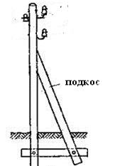
Опора деревянной одностоечной и способы укрепление угловых опор: Опоры ВЛ - конструкции, предназначенные для поддерживания проводов на необходимой высоте над землей, водой...

Своеобразие русской архитектуры: Основной материал – дерево – быстрота постройки, но недолговечность и необходимость деления...
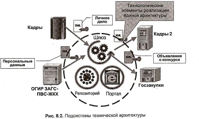
Архитектура электронного правительства: Единая архитектура – это методологический подход при создании системы управления государства, который строится...
© cyberpedia.su 2017-2024 - Не является автором материалов. Исключительное право сохранено за автором текста.
Если вы не хотите, чтобы данный материал был у нас на сайте, перейдите по ссылке: Нарушение авторских прав. Мы поможем в написании вашей работы!