
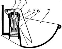
Индивидуальные и групповые автопоилки: для животных. Схемы и конструкции...
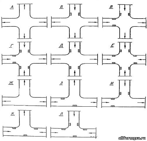
Организация стока поверхностных вод: Наибольшее количество влаги на земном шаре испаряется с поверхности морей и океанов (88‰)...
Индивидуальные и групповые автопоилки: для животных. Схемы и конструкции...
Организация стока поверхностных вод: Наибольшее количество влаги на земном шаре испаряется с поверхности морей и океанов (88‰)...
Топ:
Устройство и оснащение процедурного кабинета: Решающая роль в обеспечении правильного лечения пациентов отводится процедурной медсестре...
Эволюция кровеносной системы позвоночных животных: Биологическая эволюция – необратимый процесс исторического развития живой природы...
Интересное:
Мероприятия для защиты от морозного пучения грунтов: Инженерная защита от морозного (криогенного) пучения грунтов необходима для легких малоэтажных зданий и других сооружений...
Берегоукрепление оползневых склонов: На прибрежных склонах основной причиной развития оползневых процессов является подмыв водами рек естественных склонов...
Наиболее распространенные виды рака: Раковая опухоль — это самостоятельное новообразование, которое может возникнуть и от повышенного давления...
Дисциплины:
|
из
5.00
|
Заказать работу |
|
|
|
|
Over 2000 dead, including many port workers, and thousands more homeless. The damage sustained by the Port of Kobe, Japan’s premier port, in the earthquake disaster of 17 January has been estimated at JY940 bill or almost US$ 1 bill. Kobe port accounted for almost one fifth of all the direct and dependent jobs in the city, and the port and related industries represent almost 40 per cent of all earnings.
The earthquake had a Richter magnitude of 7.2.The seismic centre was very close to Kobe and occurred close to the surface. All the container berths under the control of Kobe Port Terminal Corporation (KPDC) on the man-made Rokko and Port Islands were put out of action, with sunken and flooded apron areas.
Only 30 of the 150 public berths managed by Kobe Port Authority could be used and just 39 of the 89 public warehouses and transit sheds were in service, to a limited extent. The Kobe Ohashi Bridge supports collapsed and the joints were damaged. It will take 2-2.5 years to restore the bridge completely and fully reopen both upper and lower level roadways.
The Maya Ohashi bridge is intact but major inspection work must be carried out before it can be reopened. Complete restoration of the Harbour Highway will take 2-3 years and work will be done in three phases (No 2 eastern industrial area to Takaha; Takaha to Maya; and Maya to Shinko No 4 Pier).
The joints of the Rokko Ohashi Bridge supports were damaged, but emergency works have been completed. There is limited access on both the upper and lower levels and complete restoration is anticipated within 9-12 months. Early estimates indicate that two years will be required to rebuild the elevated expressway which is die main artery connecting the port with Osaka and Tokyo and the only one really suitable for container trucks.
Relief supplies
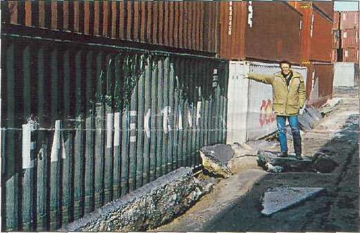
Liquefaction caused fill to settle. Sand and water erupted and splashed
against the top of this 9ft high container. (Source: Ibid)
The bridges and various quays (Hyogo No 3, Shinko No 8 east, Maya No 1) were cleared to receive emergency supplies within days of the disaster. The immediate goal is to recommission the lesser-dam aged berths within six months and restore the city and port fully within 2-3 years. Generally speaking the facilities on Rokko Island sustained less damage than those on the earlier Port Island or the Maya Terminal (the infilled Maya Piers on the mainland converted to a common user container terminal). Rokko was provided with better sand stabilisation than Port Island and therefore sustained less liquefaction damage.
According to a report by Liftech Consultants Inc, which was hired by APL to assess damage to its terminal on Port Island, the entire interior of Fort Island settled due to liquefaction of the underlying fill. The failure of the caisson wall foundation appears to be due to pressure from the liquefaction of the fill material behind the caisson and lateral seismic forces. Pending further investigations, adds Liftech, it is not clear whether the caissons rotated due to stress failure in, or liquefaction of, the underlying fill.
|
|
Road to recovery
According to the port, almost 60 public berths have become available again for conventional traffic and 14 berths for passenger traffic. Maya No 1 berth will be available for containerships at the end of March, says the port, along with seven of die KPDC berths, albeit each with just one crane. These are Port Island 2 (UASC/ Nedlloyd), 4 (both 3 and 4 were empty as NYK had just transferred completely to Rokko) and 7 and Rokko Island 1 and 2 (Sealand), 4 (Maersk) and 7 (NYK).
KPDC aims to get all its berths operating on a temporary basis with one crane each within three months and recommission the remaining cranes at 6-monthly intervals. It is understood that all the cranes will be taken back to the manufacturers' plants and fitted with new frames.
Traffic diverted

As the caisson moved out so did the waterside rail and caused the crane to spread.
On this berth one crane collapsed and the others buckled.
In the first few days following the earthquake, container traffic was diverted mainly to Tokyo (32 per cent),Yokohama (30 per cent) and nearby Osaka (25 p.er cent) which also sustained some minor damage in the quake. Containers were also diverted to Nagoya and Shimizu and die principal Korean containerport, Pusan.
If lines co-operate with each other and working practices are adjusted there should be sufficient capacity in Tokyo Bay, Osaka and Nagoya to absorb the diversion, although transhipment traffic could well be switched to ports such as Hong Kong, Kaohsiung or Pusan, particularly given the high handling charges in Japan. Some lines resumed Kobe calls within a remarkably short time (eg APL is making weekly calls with a self-sustaining vessel).
All askew
Altogether there are 46 container cranes in Kobe - 39 on Port Island and Rokko Island and seven at the Maya Terminal. The cranes at Berth C9 on Port Island (used by MOL) were inclined while the four cranes at the Sealand terminal on Rokko (RC1 and 2) were all off the rails and inclined about 20 deg to the water. At RC3 (K-Line) one gantry crane had reportedly collapsed into the sea and another collapsed onto the apron.
The cranes at the Maersk and NYK terminals (RC4-5 and RC6-7) were all inclined. There was also crane damage sustained at the Maya terminal on the mainland and in many instances the ground level had sunk on the aprons and in the CYs behind them. One container quay crane was damaged at Nanko Terminal in Osaka and the C6, C7 and C9 common user container berths were out of action for a short period. But Osaka city and pore escaped lightly compared to Kobe.
Construction report
According to the initial on-the-spot report from Liftech’s Feroze Vazifdar accompanied by a geotechnical engineer from Harza, Peter Kaldveer, the berths at Kobe are contained within perimeter quay walls and filled with reclaimed granular fill material hydraulically placed over natural sea bottom clay. The walls are made from 10m wide x 13m deep hollow concrete caissons filled with granular material. Girders for the waterside crane rails are placed over the caisson wall. The caissons were designed for a lateral coefficient of 0.lg while a seismic coefficient of 0.2g was usually specified for the container cranes.
|
|
 |
Graphical cross-section summary of Kobe port construction, with 50ft and 100ft gauge
crane rails, and earthquake consequences (Source Liftech Consultants)
A lateral force of 0.1g is lower than would normally be specified today in earthquake zones. The Pier J expansion area at Long Beach, for example, is designed to 0.2g while the structures will respond to a force of 0.33g. The wharf structure uses the so-called “structural fuse” design developed by Dames & Moore in conjunction with the port’s engineers.
The main seismic event at Kobe had a duration of 20 seconds and produced peak effective lateral accelerations near the port of 0.8g (north-south) and 0.6g (east-west) while peak vertical acceleration was 0.3g.
Unwelcome settlers
The caissons at Port Island and Maya terminal have settled between 0.7m and 3m and rotated up to 3 deg, says Liftech, which has caused the crane rails to spread. The tops of the waterside rail girders are submerged in places and the fill adjacent to the caissons has dropped an additional 2-3m.
The cranes with a 50ft gauge have their landside rail girders supported on steel piles. These have not settled appreciably but have rotated 3-5 deg in places. The cranes with a 100ft gauge have their landside rail girders on grade beams over engineered fill and these have settled in places. The crane rail girders have spread 1-2m at Port Island and 4-5m at Rokko Island.
Crane damage varies at different locations. A large number have significant structural damage and could collapse in the event of a strong aftershock. According to Liftech, the damage to the cranes is primarily due to the rails spreading and settling.
That is, it is as if the cranes were trying to “do the splits” as the quays separated and they are buckled at the portal ties. Liftech recommends that cranes are built with movement and rotation resistant ductile frames with heavy portal ties.The three MHI cranes at the APL terminal on Port Island (PC 5) were designed by Liftech and reportedly stood up well to the earthquake.
Liftech adds, however, that if the Guam earthquake of 1993 is anything to go by, it will take several months for the ground to solidify. This could cause further problems in the event of aftershocks.

The pile-supported dock structure performed well, while the caissons settled and rotated out.
Liquefaction caused the fill within the settled caissons to settle about 3ft.
Avoid catastrophe
Another firm of structural engineers, Casper, Phillips & Associates (CP&A), reports that a crane designed to meet its catastrophic load condition is able to resist the largest earthquake. A heavier and hence more costly steel structure is required but, says CP&A, when owners are asked if this is a price they are willing to pay for added protection, they usually accept it.
Having said this, the massive Kobe reconstruction project will be a fantastic consumer of steel. Steel prices seem set to rise sharply. This is bound to impact on the cost of large steel structures such as cranes and the differential between a light and a heavy crane is going to widen.
When a crane is not tied down, says CP&A, the earthquake loads are limited to the load needed to tip the crane onto two legs. Once the crane starts to lift, says Bill Casper, the load cannot increase further because the additional seismic energy is absorbed by the raising of the crane’s centre of gravity.
The crane cannot tip over because a fraction of a second later the load reverses. Earthquake tipping load is between 50 and 100 per cent of the crane weight depending on railspan and crane height. When the crane tips onto two legs they have to support the entire weight of the crane; otherwise the crane collapses and falls to the ground.
If the crane has been tied down, continues CP&A, there is no limit to the earthquake loading except that it will peak when the structure is absorbing energy as fast as seismic energy impinges on it. In a large earthquake this happens when parts of the steel structure are being plastically bent back and forth.
|
|
Earthquake forces increase in proportion to the strength of the crane, up to the severity limit of the earthquake itself. If the earthquake is strong enough to bend all four legs, the crane is likely to collapse to the ground.
From the point of view of earthquake protection, then, tying down the crane is the worst thing to do. The situation is exactly analogous to the concept of “seismic isolation” for buildings.
Exactly one year to the day before the Kobe disaster, on 17 January 1994, a 6.7 Richter scale earthquake severely damaged 31 Los Angeles area hospitals but the USC University Hospital, the world’s first “seismically isolated” building, rode out the earthquake with no damage at all.
Similarly, in the Kobe quake, the 6-storey West Japan Computer Center located 20 miles west of the city centre and one of the world’s largest seismically isolated structures (ie the equivalent of a crane free to lift on the rails), suffered no damage at all. The peak force accelerations at the roof were lower by a factor of up to 9 (ie 0.07g-0.01g compared to 0.67g-0.97g) than those of a similar-sized but conventional fixed base building (equivalent to a tied crane).
| Earthquake protection for cranes and quays will be addressed at TOC Asia in Singapore in April by Bill Casper of Casper, Phillips & Associates (CP&A) and Liftech Consultants’ Mike Jordan. CP&A has a specific crane design to cater for catastrophic loads while Liftech, whose crane designs include the Mitsubishi-built post-Panamax cranes at APL’s terminal in Kobe, was appointed by the carrier to assess the damage to its facilities in the port. Shunichi Yano, managing director of NYK Singapore Pte will also address the long term implications of the Kobe disaster at TOC Asia. NYK’s new facility on Rokko opened only last year. |
REFERENCES
Cargo systems, January 2004
Cargo systems, June 2004
Cargo systems, August 2004
Cargo systems, September 2004
Cargo systems, October 2004
Cargo systems, January/February 2005
Cargo systems, April 2005
Cargo systems, June 2005
Cargo systems, July/August 2005
Cargo systems, September 2005
Cargo systems, November 2005
WorldCargo news, February 1995
WorldCargo news, October 1995
WorldCargo news, June 1997
WorldCargo news, July 1997
WorldCargo news, August 1997
WorldCargo news, January 1998
WorldCargo news, August 2003
WorldCargo news, August 2004
WorldCargo news, November 2004
WorldCargo news, January 2005
WorldCargo news, February 2005
WorldCargo news, May 2005
WorldCargo news, June 2005
WorldCargo news, July 2005
WorldCargo news, August 2005
WorldCargo news,October 2005
International Tanker Owners Pollution Federation, Seaways, October, 2007
Seaspeak Training Manual. – Oxford: Pergamon Press, 1989. – 298 p.
IMO Resolution A.918(22). IMO standard marine communication phrases. London, 2001. – 104 p.
Стандартные фразы ИМО для общения на море. – СПб.:ЗАО ЦНИИМФ, 1997. – 476 с. («Судовладельцам и капитанам», вып. 9).
Фаворов П. А. Англо-русский морской технический словарь. – М.: Воениздат, 1977. – 931 с.
Яковлев А. А., Яковлев В. А. Основы морской технической терминологии. – Одесса: Моряк, 1977. – 100 с.
Апресян Ю. Д., Медникова Э. М., Петрова А. В. и др. Новый большой англо – русский словарь. В 3 т. Под общ. рук. Апресяна Ю. Д., Медниковой Э. М. – М.: Рус. яз., 1998. – 832 с.
|
|
CONTENTS
UNIT 1 – Cranes – part 1…………………………………………………… 3
– part 2……………………………………………...............7
– part 3…………………………………………………….12
– part 4…………………………………………………….15
– part 5…………………………………………………….18
– part 6…………………………………………………….20
– part 7…………………………………………………….22
– part 8…………………………………………………….25
– part 9…………………………………………………….28
– part 10…………………………………………………...32
– test……………………………………………………….35
UNIT 2 – Straddle carriers – part 1………………………………………….39
– part 2………………………………………….42
– part 3………………………………………….45
– part 4………………………………………….48
– test…………………………………………….50
UNIT 3 – Reach stackers – part 1……………………………………………53
– part 2…………………………………………….56
– part 3…………………………………………….59
– part 4…………………………………………….61
– part 5…………………………………………….64
– test……………………………………………….67
UNIT 4 – Tractors and other machines – part 1………………………............71
– part 2……………………………...74
– part 3………………………….......77
– part 4……………………………...79
– part 5……………………………...82
– test………………………………...85
UNIT 5 – Car carriers – part 1………………………………………………..88
– part 2…………………………………………….......91
– part 3…………………………………………...........95
– test………………………………………..................97
UNIT 6 – Forest products handling machines – part 1……………….............99
– part 2……………………...102
– part 3………………...........105
– part 4………………...........107
– part 5………………...........109
– test…………………...........111
UNIT 7 – Ports: environment and nature – part 1………………………......114
– part 2.A………………..............117
– part 2.B…………………..........119
– part 2.C………………..............122
– part 3………………..................124
– test……………………..............127
UNIT 8 – Ports of Russia……………………………………………............130
UNIT 9 – Ports of the world……………………………………...................135
UNIT 10 – Kobe earthquake – assessing the damage……………….............142
KEYS……………………………………………………………...................147
REFERENCES………………………………………….................................151
Позиция №
в плане издания
учебной литературы
МГУ на 2009 г.
Субботина Галина Николаевна,
доцент кафедры английской филологии
Субботин Михаил Владиславович,
капитан дальнего плавания
PORT CARGO HANDLING MACHINERY
Учебное пособие
________________________________________________________________________________
9,6 уч.-изд. л. Формат 60 × 84/16
Тираж 100 экз. Заказ №_________
Отпечатано в типографии ИПК МГУ имени адмирала Г. И. Невельского
690059, г. Владивосток, ул. Верхнепортовая, 50а
|
|
|
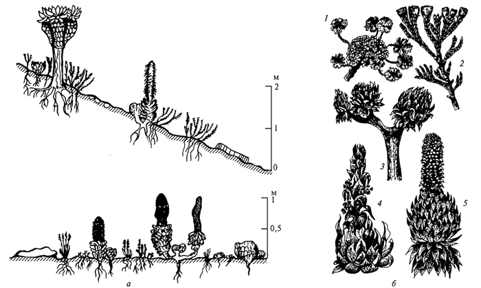
Адаптации растений и животных к жизни в горах: Большое значение для жизни организмов в горах имеют степень расчленения, крутизна и экспозиционные различия склонов...
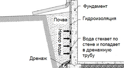
Общие условия выбора системы дренажа: Система дренажа выбирается в зависимости от характера защищаемого...
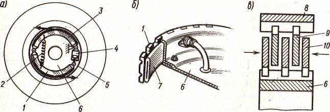
Автоматическое растормаживание колес: Тормозные устройства колес предназначены для уменьшения длины пробега и улучшения маневрирования ВС при...

Своеобразие русской архитектуры: Основной материал – дерево – быстрота постройки, но недолговечность и необходимость деления...
© cyberpedia.su 2017-2024 - Не является автором материалов. Исключительное право сохранено за автором текста.
Если вы не хотите, чтобы данный материал был у нас на сайте, перейдите по ссылке: Нарушение авторских прав. Мы поможем в написании вашей работы!