selected. 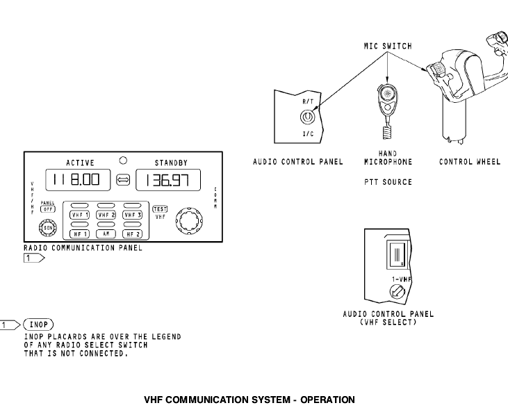
General
The VHF transceiver has built-in test equipment (BITE). You start the test on the front of the VHF transceiver.
When you start the test, the built-in test equipment examines the input from the control panel or ACARS management unit, the internal circuits and processors of the transceiver, and the output to the antenna.
Test Operation
When you push the TEST switch, the transceiver does these checks:
· Monitors the power supply
· Does a test of the memory devices устройство памяти
· Does a test of the input from the control panel or the ACARS management unit
· Does a test of the frequency synthesizer
· Keys the transmitter for 100 ms at 128.475 MHz and does a test of the modulation, power and VSWR (voltage standing wave ratio)
· Does a test of the receiver automatic-gain-control and
squelch operation.
Test Indications
Push the TEST switch to start the test. The LRU STATUS, CONTROL FAIL, and ANTENNA FAIL indicators show red for three seconds. Then, the LRU STATUS indicator shows green and the other indicators show red for three more seconds.
Then, all indicators go off for three seconds.
Then, the transceiver shows the result of the test for 30 seconds. If the LRU STATUS indicator is green and the CONTROL FAIL and ANTENNA FAIL indicators are not on, then the test result is good. If an indicator is red, then there is a failure.
The red LRU STATUS indicator comes on if there is a failure of the VHF transceiver. The red CONTROL FAIL indicator comes on if there is a failure of the signal from the control panel or the ACARS management unit. The red ANTENNA FAIL comes on if there is a failure of the antenna or the wiring between the transceiver and the antenna.

Radio Communication Panel BITE Indication
When you push the VHF switch on the radio communication panel (RCP), the display usually shows a VHF radio frequency. If the built-in test equipment in the RCP senses a failure, you see one of these displays:
INOP INOP
If the RCP receives no signal from the VHF transceiver, both displays show INOP. This occurs for these conditions:
· There is no VHF transceiver
· The VHF transceiver has no power
· The VHF transceiver can not send ARINC 429 data to the RCP
· The RCP does not receive the ARINC 429 data from the VHF transceiver
· Wiring from the VHF transceiver to the RCP is bad.
If the RCP receives the FAIL WARN signal from the VHF transceiver, both displays show FAIL. This occurs when the BITE in the VHF transceiver senses that the transceiver has a failure.
If the RCP has a failure, the active display shows PANEL and the standby display shows FAIL.

Static dischargers.
Purpose
There are static dischargers on the airplane to decrease radio receiver interference. The static dischargers discharge static at points as far from the fuselage as possible. This makes sure there is the least amout of coupling into the radio receiver
antennas.
Characteristics
Each discharger has a carbon fiber tip at the end of a slender rod. The rod is a resistive (conducting) material and attaches to a metal base. The base attaches and bonds to the airplane surface. There are trailing edge and tip dischargers. The tip dischargers are smaller than the trailing edge dischargers.
Location
The vertical fin and each wing has a tip discharger and three trailing edge dischargers. Each side of the horizontal stabilizer has a tip discharger and two trailing edge dischargers.
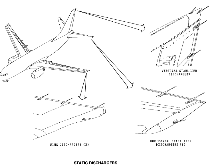
Fig. 4.5. static dischargers
Вопросы для самоконтроля.
1. Назначение УКВ радиостанции «Баклан-20».
2. Состав «Баклан-20».
3. Основные характеристики «Баклан-20».
4. Принцип действия «Баклан-20».
5. Органы управления и регулировки «Баклан-20».
6. Включение, проверка функционирования ««Баклан-20».
7. Индикация и сигнализация.
8. Какова дальность связи.
9. Вид модуляции.
10. Состав передающего тракта.
11. Состав тракта УНЧ.
12. Что происходит в ДПКД при изменении частоты на ПУ.
13. Состав тракта ПШ.
14. Когда ПШ подключает тракт УНЧ.
15. Какие каскады охвачены системой АРУ.
16. В каком диапазоне изменяется частота синтезатора в режиме приема.
17. В каком диапазоне изменяется частота синтезатора в режиме передача.
18. Какие сигналы сравниваются в ЧФД.
19. Назначение потенциометра «МОД».
20. Назначение потенциометра «СП».
21. Какие частоты вырабатывает ГУН.
22. Какие частоты вырабатывает опорный генератор.
23. Признак исправности приемного тракта.
24. Признак исправности передающего тракта.
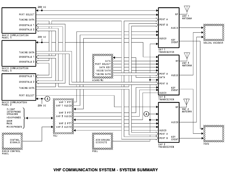
25. Назначение, состав, основные характеристики VHF communication В737.
26. Принцип работы VHF communication В737.
26. Интерфейс VHF communication В737.
27. Включение, проверка функционирования VHF communication В737.
Рекомендуемая литература.
Основная
1. Сосновский А.А., Хаймович И.А. Радиоэлектронное оборудование летательных аппаратов. Справочник – М.: Транспорт, 1987г.
2. Учебное пособие. Радиоэлектронное оборудование ЛА. Составитель Кукушин В.А. Академия ГА, 2007г.
3. Учебное пособие. COMMUNICATION СВЯЗНОЕ ОБОРУДОВАНИЕ BOEING 737-600/700/800/900. Training Manual. Составитель Кукушин В.А. Академия ГА, 2008г.
4. Учебное пособие. NAVIGATION. Part 1. НАВИГАЦИОННОЕ ОБОРУДОВАНИЕ. Часть 1. BOEING 737-600/700/800/900. Training Manual. Составитель Кукушин В.А. Академия ГА, 2008г.
5. Учебное пособие. COMMUNICATIONS СВЯЗНОЕ ОБОРУДОВАНИЕ
А-320. Training Manual. Составитель Кукушин В.А.
Дополнительная
1. Aircraft Aerodynamic, Structures and Systems. Module 13: M13.04 Communication Navigation (ATA 23/34); M13.06 Equipment and Furnishings (ATA 25) / EASA Part-66 Training Handbook. – LINK&LEARN Aviation Training GmbH, 2007. – 176 p.
2. Эксплуатационная документация на аппаратуру. (Технические описания. Инструкции по эксплуатации. АММ).