

Своеобразие русской архитектуры: Основной материал – дерево – быстрота постройки, но недолговечность и необходимость деления...
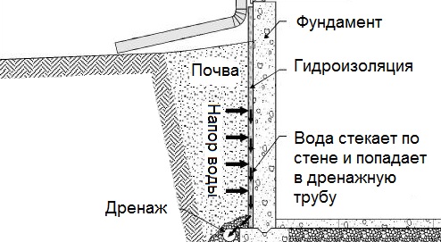
Общие условия выбора системы дренажа: Система дренажа выбирается в зависимости от характера защищаемого...
Своеобразие русской архитектуры: Основной материал – дерево – быстрота постройки, но недолговечность и необходимость деления...
Общие условия выбора системы дренажа: Система дренажа выбирается в зависимости от характера защищаемого...
Топ:
Выпускная квалификационная работа: Основная часть ВКР, как правило, состоит из двух-трех глав, каждая из которых, в свою очередь...
Отражение на счетах бухгалтерского учета процесса приобретения: Процесс заготовления представляет систему экономических событий, включающих приобретение организацией у поставщиков сырья...
Марксистская теория происхождения государства: По мнению Маркса и Энгельса, в основе развития общества, происходящих в нем изменений лежит...
Интересное:
Распространение рака на другие отдаленные от желудка органы: Характерных симптомов рака желудка не существует. Выраженные симптомы появляются, когда опухоль...
Что нужно делать при лейкемии: Прежде всего, необходимо выяснить, не страдаете ли вы каким-либо душевным недугом...
Влияние предпринимательской среды на эффективное функционирование предприятия: Предпринимательская среда – это совокупность внешних и внутренних факторов, оказывающих влияние на функционирование фирмы...
Дисциплины:
|
из
5.00
|
Заказать работу |
РОСЖЕЛДОР
Государственное образовательное учреждение
высшего профессионального образования
«Ростовский государственный университет путей сообщения»
(РГУПС)
Л.А. Свиридова, М.М. Сорокина

ТЕЛЕКОММУНИКАЦИИ
Учебно-методическое пособие
по профессионально-ориентированному чтению и обработке информации
Ростов-на-Дону
2008
УДК 42:621. 396.2(07) + 06
UNIT 1
Telecommunication
Communication ties together the parts of a society just as the nervous system ties together the parts of an individual. From earliest times, when the only form of communication was speech, to the present, when electronic signals carry information instantly to practically any point on Earth, communication has been the way people have organized their cooperative activities. In the modern world there are two main types of communications media. One type consists of the mass media — such as television, radio, newspapers, and magazines — in which organizations send messages to a large number of people. The other type consists of direct, point-to-point communications — telephone, telegraph, data transmission, and postal service. Of these, the electronic media (all but the postal service) are termed telecommunications.
Telecommunication is science and practice of transmitting information by electromagnetic means. A wide variety of information can be transferred through a telecommunications system, including voice and music, still-frame and full-motion pictures, computer files and applications, and telegraphic data Telecommunication first came into existence with the development of the telegraph in the 1830s and 1840s. For the first time, news and information could be transmitted great distances almost instantaneously. The invention of the telephone in 1876 by Alexander Graham Bell fundamentally transformed telecommunications.
After 1975, however, a new transformation of telecommunications began. The technology used to carry information changed radically.
Principles of telecommunication
Modern telecommunication centres on the problems involved in transmitting large volumes of information over long distances without damaging loss due to noise and interference. Figure 1 shows the basic components of a typical digital telecommunications system capable of transmitting voice, facsimile, data, radio, or television signals. Digital transmission is employed in order to achieve high reliability and because the cost of digital switching systems is much lower than the cost of analog systems. In order to use digital transmission, however, the analog signals that make up most voice, radio, and television communication must be subjected to a process of analog-to-digital conversion. (In data transmission this step is bypassed because the signals are already in digital form; most television, radio, and voice communication, however, use the analog system and must be digitized.) In many cases, the digitized signal is passed through a source encoder, which employs a number of formulas to reduce redundant binary information. After source encoding, the digitized signal is processed in a channel encoder, which introduces redundant information that allows errors to be detected and corrected. The encoded signal is made suitable for transmission by modulation onto a carrier wave and may be made part of a larger signal in a process known as multiplexing. The multiplexed signal is then sent into a multiple-access transmission channel. After transmission, the above process is reversed at the receiving end, and the information is extracted.
UNIT 2
Sampling
Analog-to-digital conversion begins with sampling, or measuring the amplitude of the analog waveform at equally spaced discrete instants of time. The fact that samples of a continually varying wave may be used to represent that wave relies on the assumption that the wave is constrained in its rate of variation. Because a communications signal is actually a complex wave — essentially the sum of a number of component sine waves, all of which have their own precise amplitudes and phases — the rate of variation of the complex wave can be measured by the frequencies of oscillation of all its components. The difference between the maximum rate of oscillation (or highest frequency) and the minimum rate of oscillation (or lowest frequency) of the sine waves making up the signal is known as the bandwidth (B) of the signal. Bandwidth thus represents the maximum frequency range occupied by a signal. In the case of a voice signal having a minimum frequency of 300 hertz and a maximum frequency of 3,300 hertz, the bandwidth is 3,000 hertz, or 3 kilohertz. Audio signals generally occupy about 20 kilohertz of bandwidth, and standard video signals occupy approximately 6 million hertz, or 6 megahertz.
The concept of bandwidth is central to all telecommunication. In analog-to-digital conversion, there is a fundamental theorem that the analog signal may be uniquely represented by discrete samples spaced no more than one over twice the bandwidth (1/2 B) apart. This theorem is commonly referred to as the sampling theorem, and the sampling interval (1/2 B seconds) is referred to as the Nyquist interval (after the Swedish-born American electrical engineer Harry Nyquist). In current practice 8,000 samples are taken per second, in order to increase the frequency range and the fidelity of the speech representation.
Quantization
In order for a sampled signal to be stored or transmitted in digital form, each sampled amplitude must be converted to one of a finite number of possible values, or levels. For ease in conversion to binary form, the number of levels is usually a power of 2—that is, 8, 16, 32, 64, 128, 256, and so on, depending on the degree of precision required. In Figure 2, for simplicity of illustration, an analog waveform is shown being quantized on an 8-level scale (0 through 7). In digital transmission of voice, 256 levels are commonly used because tests have shown that this provides adequate fidelity for the average telephone listener.
The input to the quantizer is a sequence of sampled amplitudes for which there are an infinite number of possible values. The output of the quantizer, on the other hand, must be restricted to a finite number of levels. This relation between infinite input and finite output is represented conceptually in Figure 2, where the signal is shown being sampled at amplitude values of 6.5, 3.3, 2.0, 2.5, and so on, but levels of 7, 3, 2, 3, and so on, are assigned in quantization. Assigning infinitely variable amplitudes to a limited number of levels inevitably introduces inaccuracy, and inaccuracy results in a corresponding amount of signal distortion. (For this reason quantization is often called a “lossy” system.) The degree of inaccuracy depends on the number of output levels used by the quantizer. More quantization levels increase the accuracy of the representation, but they also increase the storage capacity or transmission speed required. Better performance with the same number of output levels can be achieved by judicious placement of the output levels and the amplitude thresholds needed for assigning those levels. This placement in turn depends on the nature of the waveform that is being quantized. Generally, an optimal quantizer places more levels in amplitude ranges where the signal is more likely to occur and fewer levels where the signal is less likely. This technique is known as nonlinear quantization. Nonlinear quantization can also be accomplished by passing the signal through a compressor circuit, which amplifies the signal's weak components and attenuates its strong components. The compressed signal, now occupying a narrower dynamic range, can be quantized with a uniform, or linear, spacing of thresholds and output levels. In the case of the telephone signal, the compressed signal is uniformly quantized at 256 levels, each level being represented by a sequence of eight bits. At the receiving end, the reconstituted signal is expanded to its original range of amplitudes. This sequence of compression and expansion, known as companding, can yield an effective dynamic range equivalent to 13 bits.
UNIT 3
Source Encoding
As is pointed out in Analog-to-digital conversion, any available telecommunications medium has a limited capacity for data transmission. This capacity is commonly measured by the parameter which is called bandwidth. Since the bandwidth of a signal increases with the number of bits to be transmitted each second an important function of a digital communications system is to represent the digitized signal by as few bits as possible—that is, to reduce redundancy. Redundancy reduction is accomplished by a source encoder, which often operates in conjunction with the analog-to-digital converter.
Huffman codes
In general, fewer bits on the average will be needed if the source encoder takes into account the probabilities at which different quantization levels are likely to occur. A simple example will illustrate this concept. Assume a quantizing scale of only four levels: 1, 2, 3, and 4. Following the usual standard of binary encoding, each of the four levels would be mapped by a two-bit code word. But also assume that level 1 occurs 50 percent of the time, that level 2 occurs 25 percent of the time, and that levels 3 and 4 each occur 12.5 percent of the time. Using variable-bit code words, such as those also shown in the table, might cause more efficient mapping of these levels to be achieved. The variable-bit encoding rule would use only one bit 50 percent of the time, two bits 25 percent of the time, and three bits 25 percent of the time. On average it would use 1.75 bits per sample rather than the 2 bits per sample used in the standard code.
Thus, for any given set of levels and associated probabilities, there is an optimal encoding rule that minimizes the number of bits needed to represent the source. This encoding rule is known as the Huffman code, after the American D.A. Huffman, who created it in 1952. Even more efficient encoding is possible by grouping sequences of levels together and applying the Huffman code to these sequences.
The Lempel-Ziv Algorithm
The design and performance of the Huffman code depends on the designers' knowing the probabilities of different levels and sequences of levels. In many cases, however, it is desirable to have an encoding system that can adapt to the unknown probabilities of a source. A very efficient technique for encoding sources without needing to know their probable occurrence was developed in the 1970s by the Israelis Abraham Lempel and Jacob Ziv. The Lempel-Ziv algorithm works by constructing a codebook out of sequences encountered previously. For example, the codebook might begin with a set of four 12-bit code words representing four possible signal levels. If two of those levels arrived in sequence, the encoder, rather than transmitting two full code words (of length 24), would transmit the code word for the first level (12 bits) and then an extra two bits to indicate the second level. The encoder would then construct a new code word of 12 bits for the sequence of two levels, so that even fewer bits would be used thereafter to represent that particular combination of levels. The encoder would continue to read quantization levels until another sequence arrived for which there was no code word. In this case the sequence without the last level would be in the codebook, but not the whole sequence of levels. Again, the encoder would transmit the code word for the initial sequence of levels and then an extra two bits for the last level. The process would continue until all 4,096 possible 12-bit combinations had been assigned as code words.
In practice, standard algorithms for compressing binary files use code words of 12 bits and transmit 1 extra bit to indicate a new sequence. Using such a code, the Lempel-Ziv algorithm can compress transmissions of English text by about 55 percent, whereas the Huffman code compresses the transmission by only 43 percent.
Run-length Codes
Certain signal sources are known to produce “runs,” or long sequences of only 1s or 0s. In these cases it is more efficient to transmit a code for the length of the run rather than all the bits that represent the run itself. One source of long runs is the fax machine. A fax machine works by scanning a document and mapping very small areas of the document into either a black pixel (picture element) or a white pixel. The document is divided into a number of lines (approximately 100 per inch), with 1,728 pixels in each line (at standard resolution). If all black pixels were mapped into 1s and all white pixels into 0s, then the scanned document would be represented by 1,857,600 bits (for a standard 11-inch page). At older modem transmission speeds of 4,800 bits per second, it would take 6 minutes 27 seconds to send a single page. If, however, the sequence of 0s and 1s were compressed using a run-length code, significant reductions in transmission time would be made.
The code for fax machines is actually a combination of a run-length code and a Huffman code; it can be explained as follows: A run-length code maps run lengths into code words, and the codebook is partitioned into two parts. The first part contains symbols for runs of lengths that are a multiple of 64; the second part is made up of runs from 0 to 63 pixels. Any run length would then be represented as a multiple of 64 plus some remainder. For example, a run of 205 pixels would be sent using the code word for a run of length 192 (3 × 64) plus the code word for a run of length 13. In this way the number of bits needed to represent the run is decreased significantly. In addition, certain runs that are known to have a higher probability of occurrence are encoded into code words of short length, further reducing the number of bits that need to be transmitted. Using this type of encoding typical compressions for facsimile transmission range between 4 to 1 and 8 to 1. Coupled to higher modem speeds, these compressions reduce the transmission time of a single page to between 48 seconds and 1 minute 37 seconds.
UNIT 4
Channel Encoding
As described in Source encoding, one purpose of the source encoder is to eliminate redundant binary digits from the digitized signal. The strategy of the channel encoder, on the other hand, is to add redundancy to the transmitted signal — in this case so that errors caused by noise during transmission can be corrected at the receiver. The process of encoding for protection against channel errors is called error-control coding. Error-control codes are used in a variety of applications, including satellite communication, deep-space communication, mobile radio communication, and computer networking.
There are two commonly employed methods for protecting electronically transmitted information from errors. One method is called forward error control (FEC). In this method information bits are protected against errors by the transmitting of extra redundant bits, so that if errors occur during transmission the redundant bits can be used by the decoder to determine where the errors have occurred and how to correct them.
The second method of error control is called automatic repeat request (ARQ). In this method redundant bits are added to the transmitted information and are used by the receiver to detect errors. The receiver then signals a request for a repeat transmission. Generally, the number of extra bits needed simply to detect an error, as in the ARQ system, is much smaller than the number of redundant bits needed both to detect and to correct an error, as in the FEC system.
Repetition codes
One simple, but not usually implemented, FEC method is to send each data bit three times. The receiver examines the three transmissions and decides by majority vote whether a 0 or 1 represents a sample of the original signal. In this coded system, called a repetition code of block-length three and rate one-third, three times as many bits per second are used to transmit the same signal as are used by an uncoded system; hence, for a fixed available bandwidth only one-third as many signals can be conveyed with the coded system as compared with the uncoded system. The gain is that now at least two of the three coded bits must be in error before a reception error occurs.
The Hamming code
Another simple example of an FEC code is known as the Hamming code. This code is able to protect a four-bit information signal from a single error on the channel by adding three redundant bits to the signal. Each sequence of seven bits (four information bits plus three redundant bits) is called a code word.
The first redundant bit is chosen so that the sum of ones in the first three information bits plus the first redundant bit amounts to an even number. (This calculation is called a parity check, and the redundant bit is called a parity bit.)
The second parity bit is chosen so that the sum of the ones in the last three information bits plus the second parity bit is even, and the third parity bit is chosen so that the sum of ones in the first, second, and fourth information bits and the last parity bit is even. This code can correct a single channel error by recomputing the parity checks. A parity check that fails indicates an error in one of the positions checked, and the two subsequent parity checks, by process of elimination, determine the precise location of the error. The Hamming code thus can correct any single error that occurs in any of the seven positions. If a double error occurs, however, the decoder will choose the wrong code word.
UNIT 5
Convolutional Encoding
The Hamming code is called a block code because information is blocked into bit sequences of finite length to which a number of redundant bits are added. When k information bits are provided to a block encoder, n − k redundancy bits are appended to the information bits to form a transmitted code word of n bits. The entire code word of length n is thus completely determined by one block of k information bits. In another channel-encoding scheme, known as convolutional encoding, the encoder output is not naturally segmented into blocks but is instead an unending stream of bits. In convolutional encoding, memory is incorporated into the encoding process, so that the preceding M blocks of k information bits, together with the current block of k information bits, determine the encoder output. The encoder accomplishes this by shifting among a finite number of “states,” or “nodes.” There are several variations of convolutional encoding, but the simplest example may be seen in what is known as the (n, 1) encoder, in which the current block of k information bits consists of only one bit. At each given state of the (n, 1) encoder, when the information bit (a 0 or a 1) is received, the encoder transmits a sequence of n bits assigned to represent that bit when the encoder is at that current state. At the same time, the encoder shifts to one of only two possible successor states, depending on whether the information bit was a 0 or a 1. At this successor state, in turn, the next information bit is represented by a specific sequence of n bits, and the encoder is again shifted to one of two possible successor states. In this way, the sequence of information bits stored in the encoder's memory determines both the state of the encoder and its output, which is modulated and transmitted across the channel. At the receiver, the demodulated bit sequence is compared to the possible bit sequences that can be produced by the encoder. The receiver determines the bit sequence that is most likely to have been transmitted, often by using an efficient decoding algorithm called Viterbi decoding (after its inventor, A.J. Viterbi). In general, the greater the memory (i.e., the more states) used by the encoder, the better the error-correcting performance of the code — but only at the cost of a more complex decoding algorithm. In addition, the larger the number of bits (n) used to transmit information, the better the performance — at the cost of a decreased data rate or larger bandwidth.
Coding and decoding processes similar to those described above are employed in trellis coding, a coding scheme used in high-speed modems. However, instead of the sequence of bits that is produced by a convolutional encoder, a trellis encoder produces a sequence of modulation symbols. At the transmitter, the channel-encoding process is coupled with the modulation process, producing a system known as trellis-coded modulation. At the receiver, decoding and demodulating are performed jointly in order to optimize the performance of the error-correcting algorithm.
UNIT 6
Modulation
In many telecommunications systems, it is necessary to represent an information-bearing signal with a waveform that can pass accurately through a transmission medium. This assigning of a suitable waveform is accomplished by modulation, which is the process by which some characteristic of a carrier wave is varied in accordance with an information signal, or modulating wave. The modulated signal is then transmitted over a channel, after which the original information-bearing signal is recovered through a process of demodulation.Modulation is applied to information signals for a number of reasons, some of which are outlined below.
1. Many transmission channels are characterized by limited passbands — that is, they will pass only certain ranges of frequencies without seriously attenuating them (reducing their amplitude). Modulation methods must therefore be applied to the information signals in order to “frequency translate” the signals into the range of frequencies that are permitted by the channel. Examples of channels that exhibit passband characteristics include alternating-current-coupled coaxial cables, which pass signals only in the range of 60 kilohertz to several hundred megahertz, and fiber-optic cables, which pass light signals only within a given wavelength range without significant attenuation. In these instances frequency translation is used to “fit” the information signal to the communications channel.
2. In many instances a communications channel is shared by multiple users. In order to prevent mutual interference, each user's information signal is modulated onto an assigned carrier of a specific frequency. When the frequency assignment and subsequent combining is done at a central point, the resulting combination is a frequency-division multiplexed signal, as is discussed in Multiplexing. Frequently there is no central combining point, and the communications channel itself acts as a distributed combine. An example of the latter situation is the broadcast radio bands (from 540 kilohertz to 600 megahertz), which permit simultaneous transmission of multiple AM radio, FM radio, and television signals without mutual interference as long as each signal is assigned to a different frequency band.
3. Even when the communications channel can support direct transmission of the information-bearing signal, there are often practical reasons why this is undesirable. A simple example is the transmission of a three-kilohertz (i.e., voiceband) signal via radio wave. In free space the wavelength of a three-kilohertz signal is 100 kilometres (60 miles). Since an effective radio antenna is typically as large as half the wavelength of the signal, a three-kilohertz radio wave might require an antenna up to 50 kilometers in length. In this case translation of the voice frequency to a higher frequency would allow the use of a much smaller antenna.
Analog Modulation
As is noted in Analog-to-digital conversion, voice signals, as well as audio and video signals, are inherently analog in form. In most modern systems these signals are digitized prior to transmission, but in some systems the analog signals are still transmitted directly without converting them to digital form. There are two commonly used methods of modulating analog signals. One technique, called amplitude modulation, varies the amplitude of a fixed-frequency carrier wave in proportion to the information signal. The other technique, called frequency modulation, varies the frequency of a fixed-amplitude carrier wave in proportion to the information signal.
Digital modulation
In order to transmit computer data and other digitized information over a communications channel, an analog carrier wave can be modulated to reflect the binary nature of the digital baseband signal. The parameters of the carrier that can be modified are the amplitude, the frequency, and the phase.
Frequency-shift keying
If frequency is the parameter chosen to be a function of the information signal, the modulation method is called frequency-shift keying (FSK). In the simplest form of FSK signaling, shown in Figure 3, digital data is transmitted using one of two frequencies, whereby one frequency is used to transmit a 1 and the other frequency to transmit a 0. Such a scheme was used in the Bell 103 voiceband modem, introduced in 1962, to transmit information at rates up to 300 bits per second over the public switched telephone network. In the Bell 103 modem, frequencies of 1,080 +/- 100 hertz and 1,750 +/- 100 hertz were used to send binary data in both directions.
Phase-shift keying
When phase is the parameter altered by the information signal, the method is called phase-shift keying (PSK). In the simplest form of PSK, as illustrated in Figure 3, a single radio frequency carrier is sent with a fixed phase to represent a 0 and with a 180° phase shift—that is, with the opposite polarity — to represent a 1. PSK was employed in the Bell 212 modem, which was introduced about 1980 to transmit information at rates up to 1,200 bits per second over the public switched telephone network.
Advanced methods
In addition to the elementary forms of digital modulation described above, there exist more advanced methods that result from a superposition of multiple modulating signals. An example of the latter form of modulation is quadrature amplitude modulation (QAM). QAM signals actually transmit two amplitude-modulated signals in phase quadrature (i.e., 90° apart), so that four or more bits are represented by each shift of the combined signal. Communications systems that employ QAM include digital cellular systems in the United States and Japan as well as most voiceband modems transmitting above 2,400 bits per second.
A form of modulation that combines convolutional codes with QAM is known as trellis-coded modulation (TCM), which is described in Channel encoding. Trellis-coded modulation forms an essential part of most of the modern voiceband modems operating at data rates of 9,600 bits per second and above, including V.32 and V.34 modems.
UNIT 7
Multiplexing
Because of the installation cost of a communications channel, such as a microwave link or a coaxial cable link, it is desirable to share the channel among multiple users. Provided that the channel's data capacity exceeds that required to support a single user, the channel may be shared through the use of multiplexing methods. Multiplexing is the sharing of a communications channel through local combining of signals at a common point. Two types of multiplexing are commonly employed: frequency-division multiplexing and time-division multiplexing.
Time-division Multiplexing
Multiplexing also may be conducted through the interleaving of time segments from different signals onto a single transmission path — a process known as time-division multiplexing (TDM). Time-division multiplexing of multiple signals is possible only when the available data rate of the channel exceeds the data rate of the total number of users. While TDM may be applied to either digital or analog signals, in practice it is applied almost always to digital signals. The resulting composite signal is thus also a digital signal.
In a representative TDM system, data from multiple users are presented to a time-division multiplexer. A scanning switch then selects data from each of the users in sequence to form a composite TDM signal consisting of the interleaved data signals. Each user's data path is assumed to be time-aligned or synchronized to each of the other users' data paths and to the scanning mechanism. If only one bit were selected from each of the data sources, then the scanning mechanism would select the value of the arriving bit from each of the multiple data sources. In practice, however, the scanning mechanism usually selects a slot of data consisting of multiple bits of each user's data; the scanner switch is then advanced to the next user to select another slot, and so on. Each user is assigned a given time slot for all time.
Most modern telecommunications systems employ some form of TDM for transmission over long-distance routes. The multiplexed signal may be sent directly over cable systems, or it may be modulated onto a carrier signal for transmission via radio wave. Examples of such systems include the North American T carriers as well as digital point-to-point microwave systems. In T1 systems, introduced in 1962, 24 voiceband signals (or the digital equivalent) are time-division multiplexed together. The voiceband signal is a 64-kilobit-per-second data stream consisting of 8-bit symbols transmitted at a rate of 8,000 symbols per second. The TDM process interleaves 24 8-bit time slots together, along with a single frame-synchronization bit, to form a 193-bit frame. The 193-bit frames are formed at the rate of 8,000 frames per second, resulting in an overall data rate of 1.544 megabits per second. For transmission over more recent T-carrier systems, T1 signals are often further multiplexed to form higher-data-rate signals — again using a hierarchical scheme, as illustrated in Figure 4B.
UNIT 8
Multiple Access
Multiplexing is defined as the sharing of a communications channel through local combining at a common point. In many cases, however, the communications channel must be efficiently shared among many users that are geographically distributed and that sporadically attempt to communicate at random points in time. Three schemes have been devised for efficient sharing of a single channel under these conditions; they are called frequency-division multiple access (FDMA), time-division multiple access (TDMA), and code-division multiple access (CDMA). These techniques can be used alone or together in telephone systems, and they are well illustrated by the most advanced mobile cellular systems.
UNIT 9
Telecommunications Network
Telecommunications network is an electronic system of links and switches, and the controls that govern their operation, that allows for data transfer and exchange among multiple users.
When several users of telecommunications media wish to communicate with one another, they must be organized into some form of network. In theory, each user can be given a direct point-to-point link to all the other users in what is known as a fully connected topology (similar to the connections employed in the earliest days of telephony), but in practice this technique is impractical and expensive — especially for a large and dispersed network. Furthermore, the method is inefficient, since most of the links will be idle at any given time. Modern telecommunications networks avoid these issues by establishing a linked network of switches, or nodes, such that each user is connected to one of the nodes. Each link in such a network is called a communications channel. Wire, fibre-optic cable, and radio waves may be used for different communications channels.
Types of Networks
Broadcast network
A broadcast network avoids the complex routing procedures of a switched network by ensuring that each node's transmissions are received by all other nodes in the network. Therefore, a broadcast network has only a single communications channel. A wired local area network (LAN), for example, may be set up as a broadcast network, with one user connected to each node and the nodes typically arranged in a bus, ring, or star topology, as shown in the figure. Nodes connected together in a wireless LAN may broadcast via radio or optical links. On a larger scale, many satellite radio systems are broadcast networks, since each Earth station within the system can typically hear all messages relayed by a satellite.
UNIT 10
Network Access
Since all nodes can hear each transmission in a broadcast network, a procedure must be established for allocating a communications channel to the node or nodes that have packets to transmit and at the same time preventing destructive interference from collisions (simultaneous transmissions). This type of communication, called multiple access, can be established either by scheduling (a technique in which nodes take turns transmitting in an orderly fashion) or by random access to the channel.
Scheduled access
In a scheduling method known as time-division multiple access (TDMA), a time slot is assigned in turn to each node, which uses the slot if it has something to transmit. If some nodes are much busier than others, then TDMA can be inefficient, since no data are passed during time slots allocated to silent nodes. In this case a reservation system may be implemented, in which there are fewer time slots than nodes and a node reserves a slot only when it is needed for transmission.
A variation of TDMA is the process of polling, in which a central controller asks each node in turn if it requires channel access, and a node transmits a packet or message only in response to its poll. “Smart” controllers can respond dynamically to nodes that suddenly become very busy by polling them more often for transmissions. A decentralized form of polling is called token passing. In this system a special “token” packet is passed from node to node. Only the node with the token is authorized to transmit; all others are listeners.
Random access
Scheduled access schemes have several disadvantages, including the large overhead required for the reservation, polling, and token passing processes and the possibility of long idle periods when only a few nodes are transmitting. This can lead to extensive delays in routing information, especially when heavy traffic occurs in different parts of the network at different times — a characteristic of many practical communications networks. Random-access algorithms were designed specifically to give nodes with something to transmit quicker access to the channel. Although the channel is vulnerable to packet collisions under random access, various procedures have been developed to reduce this probability.
UNIT 11
Data recognition and use
The application layer is difficult to generalize, since its content is specific to each user. For example, distributed databases used in the banking and airline industries require several access and security issues to be solved at this level. Network transparency (making the physical distribution of resources irrelevant to the human user) also is handled at this level. The presentation layer, on the other hand, performs functions that are requested sufficiently often that a general solution is warranted. These functions are often placed in a software library that is accessible by several users running different applications. Examples are text conversion, data compression, and data encryption.
User interface with the network is performed by the session layer, which handles the process of connecting to another computer, verifying user authenticity, and establishing a reliable communication process. This layer also ensures that files which can be altered by several network users are kept in order. Data from the session layer are accepted by the transport layer, which separates the data stream into smaller units, if necessary, and ensures that all arrive correctly at the destination. If fast throughput is needed, the transport layer may establish several simultaneous paths in the network and send different parts of the data over each path. Conversely, if low cost is a requirement, then the layer may time-multiplex several users' data over one path through the network. Flow control is also regulated at this level, ensuring that data from a fast source will not overrun a slow destination.
Data transfer
The network layer breaks data into packets and determines how the packets are routed within the network, which nodes (if any) will check packets for errors along the route, and whether congestion control is needed in a heavily loaded network. The data-link layer transforms a raw communications channel into a line that appears essentially free of transmission errors to the network layer. This is done by breaking data up into data frames, transmitting them sequentially, and processing acknowledgment frames sent back to the source by the destination. This layer also establishes frame boundaries and implements recovery procedures from lost, damaged, or duplicated frames. The physical layer is the transmission medium itself, along with various electric and mechanical specifications.
UNIT 12
Telecommunications Media
Telecommunications media is equipment and systems — metal wire, terrestrial and satellite radio and optical fibre—employed in the transmission of electromagnetic signals.Related Content
EHide Notes
very telecommunication system involves the transmission of an information-bearing electromagnetic signal through a physical medium that separates the transmitter from the receiver. All transmitted signals are to some extent degraded by the environment through which they propagate. Signal degradation can take many forms, but generally it falls into three types: noise, distortion, and attenuation. Noise is the presence of random, unpredictable, and undesirable electromagnetic emissions that can mask the intended information signal. Distortion is any undesired change in the amplitude or phase of any component of an information signal that causes a change in the overall waveform of the signal. Both noise and distortion are commonly introduced by all transmission media, and they both result in errors in reception. The relative impact of these factors on reliable communication depends on the rate of information transmission, on the desired fidelity upon reception, and on whether communication must occur in “real time”.
Various modulating and encoding schemes have been devised to provide protection against the errors caused by channel distortion and channel noise. These techniques are described in telecommunication:analog-to-digital conversion, channel encoding, andmodulation. In addition to these signal-processing techniques, protection against reception errors can be provided by boosting the power of the transmitter, thus increasing the signal-to-noise ratio (the ratio of signal power to noise power). However, even powerful signals suffer some degree of attenuation, or reduction in power, as they pass through the transmission medium. The principal cause of power loss is dissipation, the conversion of part of the electromagnetic energy to another form of energy such as heat. In communications media, channel attenuation is typically expressed in decibels (dB) per unit distance. Attenuation of zero decibels means that the signal is passed without loss; three decibels means that the power of the signal decreases by one-half. The plot of channel attenuation as the signal frequency is varied is known as the attenuation spectrum, while the average attenuation over the entire frequency range of a transmitted signal is defined as the attenuation coefficient. Channel attenuation is an important factor in the use of each transmission medium.
UNIT 13
Wire T ransmission
In wire transmission an information-bearing electromagnetic wave is guided along a wire conductor to a receiver. Propagation of the wave is always accompanied by a flow of electric current through the conductor. Since all practical conductor materials are characterized by some electrical resistance, part of the electric current is always lost by conversion to heat, which is radiated from the wire. This dissipative loss leads to attenuation of the electromagnetic signal, and the amount of attenuation increases linearly with increasing distance between the transmitter and the receiver.
Wire media
Most modern wire transmission is conducted through the metallic-pair circuit, in which a bundled pair of conductors is used to provide a forward current path and a return current path. The most common conductor is hard-drawn copper wire, which has the benefits of low electrical resistance, high tensile strength, and high resistance to corrosion. The basic types of wire media found in telecommunications are single-wire lines, open-wire pairs, multipair cables, and coaxial cables. They are described below.
Single-wire line
In the early days of telegraphy, a single uninsulated iron wire, strung above ground, was used as a transmission line. Return conduction was provided through an earth ground. This arrangement, known as the single-wire line, was quite satisfactory for the low-frequency transmission requirements of manual telegraph signaling (only about 400 hertz). However, for transmission of higher-frequency signals, such as speech (approximately 3,000 hertz), single-wire lines suffer from high attenuation, radiation losses, and a sensitivity to stray currents induced by random fluctuations in earth ground potentials or by external interference. One common cause of external interference is natural electrical disturbances, such as lightning or auroral activity; another is cross talk, an unwanted transferral of signals from one circuit to another owing to inductive coupling between two or more closely spaced wire lines.
Multipair cable
In multipair cable anywhere from a half-dozen to several thousand twisted-pair circuits are bundled into a common sheath (see Figure 1). The twisted pair was developed in the late 19th century in order to reduce cross talk in multipair cables. In a process similar to that employed with open-wire pairs (described above), the forward and return conductors of each circuit in a multipair cable are braided together, equalizing the relative positions of all the circuits in the cable and thus equalizing currents induced by cross talk.
For many high-speed and high-density applications, such as computer networking, each wire pair is sheathed in metallic foil. Sheathing produces a balanced circuit, called a shielded pair that benefits from greatly reduced radiation losses and immunity to cross talk interference.
Coaxial cable
By enclosing a single conducting wire in a dielectric insulator and an outer conducting shell, an electrically shielded transmission circuit called coaxial cable is obtained. As is shown in Figure 1, in a coaxial cable the electromagnetic field propagates within the dielectric insulator, while the associated current flow is restricted to adjacent surfaces of the inner and outer conductors. As a result, coaxial cable has very low radiation losses and low susceptibility to external interference.
In order to reduce weight and make the cable flexible, tinned copper or aluminum foil is commonly used for the conducting shell. Most coaxial cables employ a lightweight polyethylene or wood pulp insulator; although air would be a more effective dielectric, the solid material serves as a mechanical support for the inner conductor.
Applications of wire
Because of the high signal attenuation inherent in wire, transmission over distances greater than a few kilometres requires the use of regularly spaced repeaters to amplify, restore, and retransmit the signal. Transmission lines also require impedance matching at the transmitter or receiver in order to reduce echo-creating reflections. Impedance matching is accomplished in long-distance telephone cables by attaching a wire coil to each end of the line whose electrical impedance, measured in ohms, is equal to the characteristic impedance of the transmission line. A familiar example of impedance matching is the transformer used on older television sets to match a 75-ohm coaxial cable to antenna terminals made for a 300-ohm twin-lead connection.
Coaxial cable is classified as either flexible or rigid. Standard flexible coaxial cable is manufactured with characteristic impedance ranging from 50 to 92 ohms. The high attenuation of flexible cable restricts its utility to short distances— e.g., spans of less than one kilometer, or approximately a half-mile—unless signal repeaters are used. For high-capacity long-distance transmission, a more efficient wire medium is rigid coaxial cable, which was favoured for telephone transmission until it was supplanted by optical fibres in the 1980s. A state-of-the-art rigid coaxial telephone cable is the transatlantic SG series cable; the third cable in the series, called TAT-6, was laid in 1976 by the American Telephone & Telegraph Company (AT&T) between the east coast of the United States and the west coast of France. Capable of carrying 4,200 two-way voice circuits, the SG system has solid-state repeaters embedded in the cable housing at intervals of 9.5 kilometres (5.75 miles) and has equalizers that can be remotely adjusted to compensate for time-varying transmission characteristics.
Long-distance telephone cable is being phased out in favour of higher-performance optical fibre cable. Nevertheless, the last generation of long-distance telephone cable is still used to carry voice communication as well as broadband audio and video signals for cable television providers. For short-distance applications, where medium bandwidth and low-cost point-to-point communication is required, twisted pair and coaxial cable remain the standard. Voice-grade twisted pair is used for local subscriber loops in the public switched telephone network, and flexible coaxial cable is commonly used for cable television connections from curbside to home. Flexible coaxial cable also has been used for local area network interconnections, but it has largely been replaced with lighter and lower-cost data-grade twisted pair and optical fibre.
UNIT 14
Radio T ransmission
In radio transmission a radiating antenna is used to convert a time-varying electric current into an electromagnetic wave or field, which freely propagates through a nonconducting medium such as air or space. In a broadcast radio channel, an omnidirectional antenna radiates a transmitted signal over a wide service area. In a point-to-point radio channel, a directional transmitting antenna is used to focus the wave into a narrow beam, which is directed toward a single receiver site. In either case the transmitted electromagnetic wave is picked up by a remote receiving antenna and reconverted to an electric current.
Radio wave propagation is not constrained by any physical conductor or waveguide. This makes radio ideal for mobile communications, satellite and deep-space communications, broadcast communications, and other applications in which the laying of physical connections may be impossible or very costly. On the other hand, unlike guided channels such as wire or optical fibre, the medium through which radio waves propagate is highly variable, being subject to diurnal, annual, and solar changes in the ionosphere, variations in the density of water droplets in the troposphere, varying moisture gradients, and diverse sources of reflection and diffraction.
Radio-wave propagation
The range of a radio communications link is defined as the farthest distance that the receiver can be from the transmitter and still maintain a sufficiently high signal-to-noise ratio (SNR) for reliable signal reception. The received SNR is degraded by a combination of two factors: beam divergence loss and atmospheric attenuation. Beam divergence loss is caused by the geometric spreading of the electromagnetic field as it travels through space. As the original signal power is spread over a constantly growing area, only a fraction of the transmitted energy reaches a receiving antenna. For an omnidirectional radiating transmitter, which broadcasts its signal as an expanding spherical wave, beam divergence causes the received field strength to decrease by a factor of 1/ r 2, where r is the radius of the circle, or the distance between transmitter and receiver.
The other cause of SNR degradation, atmospheric attenuation, depends on the propagation mechanism, or the means by which unguided electromagnetic waves travel from transmitter to receiver. Radio waves are propagated by a combination of three mechanisms: atmospheric wave propagation, surface wave propagation, and reflected wave propagation. They are described below.
Atmospheric Propagation
In atmospheric propagation the electromagnetic wave travels through the air along a single path from transmitter to receiver. The propagation path can follow a straight line, or it can curve around edges of objects, such as hills and buildings, by ray diffraction. Diffraction permits cellular telephones to work even when there is no line-of-sight transmission path between the radiotelephone and the base station.
The attenuation spectrum of electromagnetic waves are propagated along horizontal paths over land. A broad range of the attenuation spectrum is shown, from microwave radio to ultraviolet light. Atmospheric attenuation is not significant for radio frequencies below 10 gigahertz. Above 10 gigahertz under clear air conditions, attenuation is caused mainly by atmospheric absorption losses; these become large when the transmitted frequency is of the same order as the resonant frequencies of gaseous constituents of the atmosphere, such as oxygen (O2), water vapour (H2O), and carbon dioxide (CO2) (shown by the spiked curves in Figure 2). The valleys between the peaks of the solid curves are spectral “windows,” which specify frequency bands where transmission occurs with minimal clear-air absorption losses. Additional losses due to scattering occur when airborne particles, such as water droplets or dust, present cross-sectional diameters that are of the same order as the signal wavelengths. Scattering loss due to heavy rainfall (shown by the line labeled “heavy rain 50 mm/hr”) is the dominant form of attenuation for radio frequencies ranging from 10 gigahertz to 500 gigahertz (microwave to submillimetre wavelengths), while scattering loss due to fog (shown by the dotted line) dominates for frequencies ranging from 103 gigahertz to 106 gigahertz (infrared through visible light range).
Reflected Propagation
Sometimes part of the transmitted wave travels to the receiver by reflection off a smooth boundary whose edge irregularities are only a fraction of the transmitted wavelength. When the reflecting boundary is a perfect conductor, total reflection without loss can occur. However, when the reflecting boundary is a dielectric, or nonconducting material, part of the wave may be reflected while part may be transmitted (refracted) through the medium — leading to a phenomenon known as refractive loss. When the conductivity of the dielectric is less than that of the atmosphere, total reflection can occur if the angle of incidence (that is, the angle relative to the normal, or a line perpendicular to the surface of the reflecting boundary) is less than a certain critical angle.
Common forms of reflected wave propagation are ground reflection, where the wave is reflected off land or water, and ionospheric reflection, where the wave is reflected off an upper layer of the Earth's ionosphere (as in shortwave radio).
Some terrestrial radio links can operate by a combination of atmospheric wave propagation, surface wave propagation, ground reflection, and ionospheric reflection. In some cases this combining of propagation paths can produce severe fading at the receiver. Fading occurs when there are significant variations in received signal amplitude and phase over time or space. Fading can be frequency-selective — that is, different frequency components of a single transmitted signal can undergo different amounts of fading. A particularly severe form of frequency-selective fading is caused by multipath interference, which occurs when parts of the radio wave travel along many different reflected propagation paths to the receiver. Each path delivers a signal with a slightly different time delay, creating “ghosts” of the originally transmitted signal at the receiver. A “deep fade” occurs when these ghosts have equal amplitudes but opposite phases — effectively canceling each other through destructive interference. When the geometry of the reflected propagation path varies rapidly, as for a mobile radio traveling in an urban area with many highly reflective buildings, a phenomenon called fast fading results. Fast fading is especially troublesome at frequencies above one gigahertz, where even a few centimetres of difference in the lengths of the propagation paths can significantly change the relative phases of the multipath signals. Effective compensation for fast fading requires the use of sophisticated diversity combining techniques, such as modulation of the signal onto multiple carrier waves, repeated transmissions over successive time slots, and multiple receiving antennas.
UNIT 15
VLF-MF
The very low frequency to medium frequency (VLF-MF) bands extend from three kilohertz to three megahertz, or wavelengths of 100 kilometres to 100 metres. These bands are used for low-bandwidth analog services such as long-distance radio navigation, maritime telegraph and distress channels, and standard AM radio broadcasting. Owing to insufficient available bandwidth, they are unsuitable for broadband telecommunication services such as television and FM radio. Because of the high conductivity of salt water, maritime radio transmissions at VLF can propagate via surface waves for thousands of kilometres.
HF
High-frequency (HF) radio is in the 100- to 10-metre wavelength band, extending from 3 megahertz to 30 megahertz. Much of the HF band is allocated to mobile and fixed voice communication services requiring transmission bandwidths of less than 12 kilohertz. International (shortwave radio) broadcasting also is conducted in the HF band; it is allocated to seven narrow bands between 5.9 megahertz and 26.1 megahertz.
The primary mode of propagation for HF radio transmissions is reflection off the ionosphere, a series of ionized layers of the atmosphere ranging in altitude from 50 to 300 kilometres above the Earth. Ionization is caused primarily by radiation from the Sun, so that the layers vary in height and in reflectivity with time. During the day the ionosphere consists of four layers located at average altitudes of 70 kilometres (D layer), 110 kilometres (E layer), 200 kilometres (F1 layer), and 320 kilometres (F2 layer). At night the D and E layers often disappear, and the F1 and F2 layers combine to form a single layer at an average altitude of 300 kilometres. Reflective conditions thus change with time. During the day an HF radio wave can reflect off the E, F1, or F2 layers. At night, however, it can reflect only off the high-altitude F layer, creating very long transmission ranges. (The D layer is nonreflecting at HF frequencies and merely attenuates the propagating radio wave.) In the lower HF band, transmission ranges of many thousands of kilometres can be achieved by multiple reflections, called skips, between the Earth and layers of the ionosphere.
Strong ionospheric reflections occur only below a maximum usable frequency (MUF), which is determined by the zenith angle of the incident ray and by the ionization density of the reflecting layer. In general, the MUF is higher at larger zenith angles and higher ionization densities. During the peaks of the 11-year sunspot cycle, solar ultraviolet radiation produces the highest ionization densities. These sunspot peaks can last several days or months, depending on the persistence of sunspot visibility, producing a sporadic E layer that often can be used for multiple-skip communications by amateur radio operators at frequencies up to 144 megahertz—well into the VHF band.
VHF-UHF
The very high frequency to ultrahigh frequency (VHF-UHF) bands are in the wavelength range of 10 metres to 10 centimetres, extending from 30 megahertz to 3 gigahertz. Some of these bands are used for broadcast services such as FM radio, VHF television (54–88 megahertz for channels 2–6, 174–220 megahertz for channels 7–13), and UHF television (frequency slots scattered within 470–806 megahertz). The UHF band also is used for studio and remote-pickup television relays, microwave line-of-sight links (1.7–2.3 gigahertz), and cellular telephony (806–890 megahertz). Parts of the band are used for radio navigation applications, such as instrument landing systems (108–112 megahertz), military aircraft communications (225–400 megahertz), air traffic control radio beacons (1.03–1.09 gigahertz), and the satellite-based Navstar global positioning system (1.575-gigahertz uplink and 1.227-gigahertz downlink).
Powerful UHF transmitters can achieve beyond-the-horizon transmission ranges by scattering transmitted energy off layers of the troposphere (the lowest layer of the atmosphere, where most clouds and weather systems are contained). Unlike signals in the longer-wavelength HF band, for which layers in the atmosphere appear as relatively smooth reflective surfaces, signals in the shorter-wavelength UHF band reflect off small irregularities in the atmospheric layers as if these irregularities were randomly oriented granular reflectors. The reflectors disperse the propagating UHF signal in many directions, so that only a fraction of the transmitted signal power may reach the receiver. In addition, owing to unpredictable disturbances in atmospheric conditions, significant fading can occur over a given path, at a given time, and at a given radio frequency. For this reason a tropospheric scatter relay typically uses combinations of space, time, and frequency diversity techniques. A typical relay links two large terminals across spans of 320 to 480 kilometres (200 to 300 miles) and carries up to 100 voice channels.
SHF-EHF
The superhigh frequency to extremely high frequency (SHF-EHF) bands are in the centimetre to millimetre wavelength range, which extends from 3 gigahertz to 300 gigahertz. Typical allocated bandwidths in the SHF band range from 30 megahertz to 300 megahertz—bandwidths that permit high-speed digital communications (up to 1 gigabit per second). In addition to degradation from fading and from atmospheric attenuation radio waves in the SHF-EHF band undergo high penetration losses as they propagate through the exterior walls of buildings. Because of the severe atmospheric attenuation, and in particular rainfall scattering losses, the EHF band is currently the least populated radio band for terrestrial communication. However, it has been used for intersatellite communication and satellite radionavigation—applications in which atmospheric attenuation is not a factor.
UNIT 16
UNIT 17
Satellite Links
A telecommunications satellite is a sophisticated space-based cluster of radio repeaters, called transponders, that link terrestrial radio transmitters to terrestrial radio receivers through an uplink (a link from terrestrial transmitter to satellite receiver) and a downlink (a link from satellite transmitter to terrestrial receiver). Most telecommunications satellites have been placed in geostationary orbit (GEO), a circular orbit 35,785 kilometres (22,235 miles) above the Earth in which the period of their revolution around the Earth equals the period of the Earth's rotation. Remaining thus fixed above one point on the Earth's surface (in virtually all cases, above the Equator), GEO satellites can view a stationary patch covering more than one-third of the globe. By virtue of such a wide area of coverage, GEO satellites can deliver a variety of telecommunications services, such as long-distance point-to-point transmission, wide area broadcasting (from a single transmitter to multiple receivers), or wide area report-back services (from multiple transmitters to a single receiver). Modern GEO satellites have several microwave transmitter and receiver antennas, which allow a s
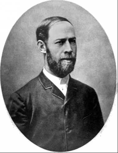
История создания датчика движения: Первый прибор для обнаружения движения был изобретен немецким физиком Генрихом Герцем...
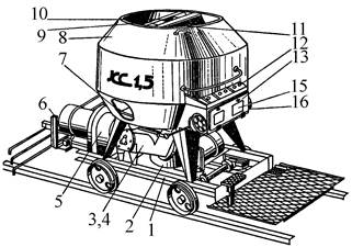
Кормораздатчик мобильный электрифицированный: схема и процесс работы устройства...
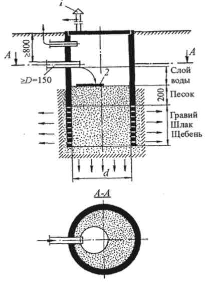
Индивидуальные очистные сооружения: К классу индивидуальных очистных сооружений относят сооружения, пропускная способность которых...
Индивидуальные и групповые автопоилки: для животных. Схемы и конструкции...
© cyberpedia.su 2017-2024 - Не является автором материалов. Исключительное право сохранено за автором текста.
Если вы не хотите, чтобы данный материал был у нас на сайте, перейдите по ссылке: Нарушение авторских прав. Мы поможем в написании вашей работы!