
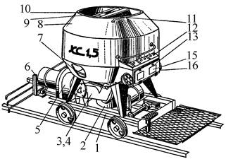
Кормораздатчик мобильный электрифицированный: схема и процесс работы устройства...
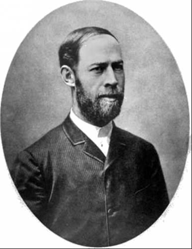
История создания датчика движения: Первый прибор для обнаружения движения был изобретен немецким физиком Генрихом Герцем...
Кормораздатчик мобильный электрифицированный: схема и процесс работы устройства...
История создания датчика движения: Первый прибор для обнаружения движения был изобретен немецким физиком Генрихом Герцем...
Топ:
Методика измерений сопротивления растеканию тока анодного заземления: Анодный заземлитель (анод) – проводник, погруженный в электролитическую среду (грунт, раствор электролита) и подключенный к положительному...
Характеристика АТП и сварочно-жестяницкого участка: Транспорт в настоящее время является одной из важнейших отраслей народного хозяйства...
Особенности труда и отдыха в условиях низких температур: К работам при низких температурах на открытом воздухе и в не отапливаемых помещениях допускаются лица не моложе 18 лет, прошедшие...
Интересное:
Финансовый рынок и его значение в управлении денежными потоками на современном этапе: любому предприятию для расширения производства и увеличения прибыли нужны...
Отражение на счетах бухгалтерского учета процесса приобретения: Процесс заготовления представляет систему экономических событий, включающих приобретение организацией у поставщиков сырья...
Аура как энергетическое поле: многослойную ауру человека можно представить себе подобным...
Дисциплины:
|
из
5.00
|
Заказать работу |
|
|
|
|
Various factors affect the reliability of a substation or switchyard, one of which is the arrangement of the buses and switching devices. In addition to reliability, arrangement of the busses/switching devices will impact maintenance, protection, initial substation development, and cost.
There are six types of substation bus/switching arrangements commonly used in air insulated substations: single bus; double bus, double breaker; main and transfer (inspection) bus; double bus, single breaker; ring bus; breaker and a half.
Single Bus. This arrangement involves one main bus with all circuits directly to the bus. The reliability of this type of an arrangement is very low. When properly protected by relaying, a single failure to the main bus or any circuit section between its circuit breaker and the main bus will cause an outage of the entire system. In addition, maintenance of devices on this system requires the de-energizing of the line connected to the device. Since the single bus arrangement is low in reliability, it is not recommended for heavily loaded substations. Reliability of this arrangement can be improved by the addition of a bus tiebreaker to minimize the effect of a main bus failure.
Double Bus, Double Breaker. This scheme provides a very high level of reliability by having two separate breakers available to each circuit. In addition, with two separate buses, failure of a single bus will not impact either line. Maintenance of a bus or a circuit breaker in this arrangement can be accomplished without interrupting either of the circuits. This arrangement allows various operating options as additional lines are added to the arrangement; loading on the system can be shifted by connecting lines to only one bus. A double bus, double breaker scheme is a high-cost arrangement, since each line has two breakers and requires a larger area for the substation to accommodate the additional equipment.
Main and Transfer Bus. This scheme is arranged with all circuits connected between a main (operating) bus and a transfer bus (also referred to as an inspection bus).Some arrangements include a bus tie breaker that is connected between both buses with no circuits connected to it. Since all circuits are connected to the single, main bus, reliability of this system is not very high. However, with the transfer bus available during maintenance, de-energizing of the circuit can be avoided. When maintenance work is necessary, the transfer bus is energized by either closing the tie breaker, or when a tie breaker is not installed, closing the switches connected to the transfer bus. With these switches closed, the breaker to be maintained can be opened along with its isolation switches. Then the breaker is taken out of service. The circuit remaining in service will now be connected to both circuits through the transfer bus. This way, both circuits remain energized during maintenance. Since each circuit may have a different circuit configuration, special relay settings may be used when operating in this abnormal arrangement. When a bus tie breaker is present, the bus tie breaker is the breaker used to replace the breaker being maintained, and the other breaker is not connected to the transfer bus. A shortcoming of this scheme is that if the main bus is taken out of service, even though the circuits can remain energized through the transfer bus and its associated switches, there would be no relay protection for the circuits. Depending on the system arrangement, this concern can be minimized through the use of circuit protection devices (reclosure or fuses) on the lines outside the substation. This arrangement is slightly more expensive than the single bus arrangement, but does provide more flexibility during maintenance. Protection of this scheme is similar to that of the single bus arrangement.
|
|
Double Bus, Single Breaker. This scheme has two main buses connected to each line circuit breaker and a bus tie breaker. Utilizing the bus tie breaker in the closed position allows the transfer of line circuits from bus by means of the switches. This arrangement allows the operation of the circuits from either bus. In this arrangement, a failure on one bus will not affect the other bus. However, a bus tie breaker failure will cause the outage of the entire system. Relay protection for this scheme can be complex, depending on the system requirements, flexibility, and needs.
Ring Bus. In this scheme, as indicated by the name, all breakers are arranged in a ring with circuits tapped between breakers. For failure on a circuit, the two adjacent breakers will trip without affecting the rest of the system. In order to gain the highest reliability with a ring bus scheme, load and source circuits should be alternated when connecting to the scheme. Arranging the scheme in this manner will minimize the potential for the loss of the supply to the ring bus do to a breaker failure. Relaying is more complex in this scheme that some previously identified. Since there is only one bus in this scheme, the area required to develop this scheme is less than some of the previously discussed schemes.
Breaker-and-a-Half. The breaker-and-a-half scheme can be developed from a ring bus arrangement as the number of circuits increase. In this scheme, each circuit is between two circuit breakers, and there are two main buses. The failure of a circuit will trip the two adjacent breakers and not interrupt any other circuit. With the three breaker arrangement for each bay, a center breaker failure will cause the loss of the two adjacent circuits. However, a breaker failure of the breaker adjacent to the bus will only interrupt one circuit. Maintenance of a breaker on this scheme can be performed without an outage to any circuit. Furthermore, either bus can be taken out service with no interruption to the service. This is one of the most reliable arrangements, and it can continue to be expanded if required. Relaying is more involved than some schemes previously discussed. This scheme will require more area and is costly due to the additional components.
1. Read and translate the text.
2. Answer the following questions to the text.
1). What affects the reliability of a substation?
2). Which type of bus/switching arrangements has the lowest reliability?
3). What makes the double bus, double breaker scheme more reliable?
4). What are the disadvantages of the double bus, double breaker arrangement?
5). What is the main weakness of the main and transfer bus scheme?
|
|
6). What helps to minimize the potential for the loss of the supply in the ring bus arrangement?
7). Why is the breaker-and-a-half scheme called one of the most reliable arrangements?
3. Complete the sentences with the missing information.
1). The single bus arrangement is not recommended for heavily loaded substations …
2). If we compare the cost of the main and transfer bus arrangement and the single bus arrangement …
3). In double bus, single breaker scheme the outage of the entire system …
4). If there is a failure of a circuit in the breaker-and-a-half scheme …
4. Rearrange the letters to form a word and match the word to its definition.
| Eg.: eldeandi | deadline | time or date when something must be finished |
| a) usb | 1). breakdown | |
| b) yaler | 2). an interruption of the power supply | |
| c) atsitsonub | 3). an electrical conductor, maintained at a specific voltage and capable of carrying a high current, usually used to make a common connection between several circuits in a system | |
| d) refialu | 4).maintenance | |
| e) iversec | 5). an electrical device such that current flowing through it in one circuit can switch on and off a current in a second circuit | |
| f) ogetau | 6). a branch station where electrical current is converted |
5. Find the antonyms.
| 1). costly | a). distant |
| 2). abnormal | b). common |
| 3). slightly | c). cheap |
| 4). adjacent | d). insignificant |
| 5). initial | e). heavily |
| 6). special | f). final |
6 Describe any type of the bus/switching arrangements used in AIS.
|
|
|
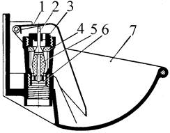
Индивидуальные и групповые автопоилки: для животных. Схемы и конструкции...
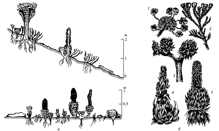
Адаптации растений и животных к жизни в горах: Большое значение для жизни организмов в горах имеют степень расчленения, крутизна и экспозиционные различия склонов...
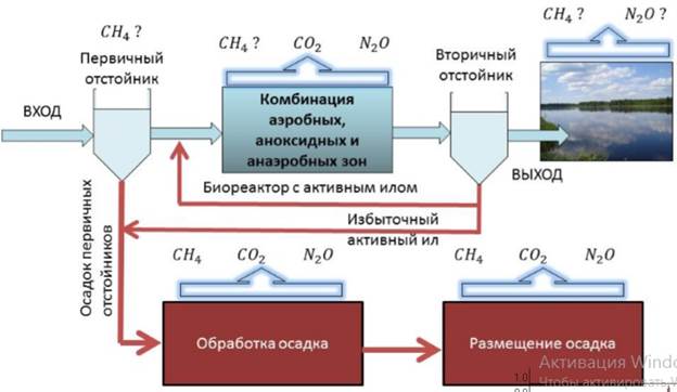
Эмиссия газов от очистных сооружений канализации: В последние годы внимание мирового сообщества сосредоточено на экологических проблемах...
Кормораздатчик мобильный электрифицированный: схема и процесс работы устройства...
© cyberpedia.su 2017-2024 - Не является автором материалов. Исключительное право сохранено за автором текста.
Если вы не хотите, чтобы данный материал был у нас на сайте, перейдите по ссылке: Нарушение авторских прав. Мы поможем в написании вашей работы!